• The move to the new server is done. There are some software and database maintenance updates in process. This has us passing the hat around to help out. We appreciate any donations. Seriously, even a dollar helps. The payment page may be found here - https://www.audiokarma.org/support.html

Yamaha A-1 JDM ( Silver face ) restoration .

@mbz

I spent some time using adobe inDesign to make a chart of the voltages
with the schematic next to it for easy reference.

I'll post a large size here and a link to the Flickr page if you want to see larger size.

Click on size links in flickr to get larger if need be.

https://www.flickr.com/photos/21885221@N04/51855495919/sizes/k/

Click to expand.

51855495919_b68893e7d4_k.jpg


Maybe you or @avionic will have some revelation ;) lol

Edit, (Not related to Pre issue butt he earlier idle current issue )
Now the relay will click on and off sporadically and those high voltages are mostly gone but the low once oscillate . Scope will need to be hooked up once we get the Pre issue fixed

Athanasios
 

Attachments

Just some house keeping, can you remeasure b then e voltages to GND for TR414. Looks like an error from previous measurement,
upload_2022-2-1_15-59-21.png

Likewise IC401 Gate 2, previous was mV but with 33V at TP1, expect 10s of volts.

EDIT: What about VR401..., new trimmers in post #24.
Measure resistance between two non-wiper legs, expect 100ohms. Then between wiper and each other leg in turn. Compare with VR402/are they set about the same?

D405 is at the limits of the spec, 6.35V against max spec of 6.4V. D406 is spot on at 5.8V, include a replacement on your next order. Both D405,6 result in 1mA through R413,4 so very unlikely to be cause.
 
Last edited:
Just some house keeping, can you remeasure b then e voltages to GND for TR414. Looks like an error from previous measurement,
View attachment 2471041

Likewise IC401 Gate 2, previous was mV but with 33V at TP1, expect 10s of volts.

EDIT: What about VR401..., new trimmers in post #24.
Measure resistance between two non-wiper legs, expect 100ohms. Then between wiper and each other leg in turn. Compare with VR402/are they set about the same?


D405 is at the limits of the spec, 6.35V against max spec of 6.4V. D406 is spot on at 5.8V, include a replacement on your next order. Both D405,6 result in 1mA through R413,4 so very unlikely to be cause.

TR414
b= -33.62
e= -32.98

IC401
Pin 2 =Gate=104 mv

I removed VR401 and it measured fine and then set it to 50 ohms and reinstalled . Still not able to change voltage.

VR402 adjusts even though test point is not stable, tried to lower it, It was jumping from 1.xx to 2.xx got it to jump around -100mV to + 200mV but after some time it drifted back to over a volt .

I have had the speaker switch turned off for some of the previous testing and these latest have been with Speaker on. But before I guess it didn't matter as the relay would not click. But now its going off and on. I try to wait for it to be in the one state.

Also I found in MC mode the test pint T1 will go from 33 to 12 or so. Actually both test points drop.

EDIT. I also just found that It has the opposite affect on the right channel, the voltage goes from under .4 vdc UP to 2.xx vdc . maybe thats a clue?

It wasn't the disc switch that affected it, so its the MC .

Going to see if changing D 401 will do anything.

Athanasios
 
Last edited:
  • Like
Reactions: mbz
Thanks for those measurements.


This looks odd, maybe compare IC401 Gate 1/R405 voltage in both MM and MC? Also compare with IC402.

IC 401
in MM
Pin 2= .64 mV
In MC
Pin2= 5.5mV

IC402
in MM
Pin2= 8 mV
In MC
Pin2= 4.6 mV


Nashou
 
Those voltages don't look "significant" to cause such a change in offset.
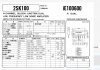
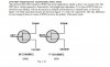
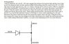
Datasheet (clinicaudio) and test procedure (echowars) for your library
2SK100_datasheet.JPGJFET1.JPG JFET1.JPG

Need to step out for a few hours.
 

Attachments

  • JFET2.JPG
    JFET2.JPG
    82.8 KB · Views: 16
Results of Curve tracer. To me it looks good, but what do I know ;)

51856974818_61058c373c_o.jpg

51857220624_033f2d3c59_b.jpg

51857220559_5d4e2c9549_b.jpg


51855932442_346447dd19_o.jpg


51856974798_7caf5e588a_b.jpg


51855932452_53c645d658_b.jpg


When I removed it the pins were very black and corroded. I cleaned them down to being silver and reinstalled.

Not sure what I did but voltages dropped at TP1 to 9.47 , as did the voltages at the b and e of TR 415,417
and the colectors of te others also lowered. But with MC pressed this time they went p to 12.xx VDC ?

I think im going to remove ic402 as well and clean those pins too.

Nashou
 
  • Like
Reactions: mbz
Ok I was able to adjust both the VR's now to +/- 200mv per the manual .

Not sure what was done by removing and cleaning the 2SK100's but it must have been the trick.

Lets see how long this lasts. Im leaving the amp on for at least 30 minutes even though the relay clicks on and off every 20 seconds or so.

Nashou
 
Wow, you're deep into the trouble-shooting. I don't have the skills to offer input but the 20sec relay click - sounds like a cap? Perhaps one of the ones replaced.
But hey, I'm following your troubleshooting and sometimes it just requires keeping at it.
 
Wow, you're deep into the trouble-shooting. I don't have the skills to offer input but the 20sec relay click - sounds like a cap? Perhaps one of the ones replaced.
But hey, I'm following your troubleshooting and sometimes it just requires keeping at it.

Took years of just diving in and I also like to follow many posts of others trouble shooting.
So thank you . Persistence is key , however some times you need to walk away for a while and work on something else then return to it.

Nashou
 
So the offset moved a little and needed a few more times adjusting it.

However putting it into MC mode raises the offset of that board quite a bit out of the mV range.
Any ideas why this would be? I checked for any voltages on the MC input switch and there were none
that I remember ( writing this after a long break ) .
Maybe its not an issue?

So now its either onto diagnosing the drive board or electrolytic board or do they work in tandem ? I think its the latter. I did find one of the traces lifted off the board on the left channel drive but did not break and still
had continuity . It was the -O pin that broke out of it header . I added some CA glue to the trace side under the through hole pad and hope it hold for a bit. I will add hot glue to the top side pins to hold the to the board.

Now the voltages there have all dropped from what they were when i posted these voltages below.

51842594382_9c3b769821_b.jpg


So those are no longer the case. Tomorrow i will measure again and document them, but many oscillate and are not stable.

See you all tomorrow in about 17 hours . Thats abider the time difference from Me to @mbz !!!

And thanks for your help so far mbz , I learned a lot .

Nashou
 
However putting it into MC mode raises the offset of that board quite a bit out of the mV range.
Any ideas why this would be?
IC 401
in MM
Pin 2= .64 mV
In MC
Pin2= 5.5mV

IC402
in MM
Pin2= 8 mV
In MC
Pin2= 4.6 mV
I need to have a look at the datasheet but 5mV does not seem significant to me.
EDIT: Curves in post #130 shows a 5mV change in Vgs has a very minor (0.2mA) change on drain current. Need some fresh eyes to look at it...
 
Last edited:
I need to have a look at the datasheet but 5mV does not seem significant to me.


At TP1 and 2 in MC mode IIRC it went to almost or past .5 vdc.

I'll check tomorrow . Typing this while in bed.

Athanasios
 
At TP1 and 2 in MC mode IIRC it went to almost or past .5 vdc.

I'll check tomorrow . Typing this while in bed.

Athanasios


@mbz , In mm mode on the pre the offset is the spec'd range drifting up and down but with in the +/_ 200mV range.
When MC is engaged they both jump to over 1.7 vdc.

Now for the idle current . Right side is still good, left side drifts a bit up and down but can be changed . However when the speaker relay is depressed out and the speakers
are switched off the idle current stabilizes pretty well . A clue maybe? When relay is pressed for speakers to work it will go off and on regularly .

The Drive board adjustments are still jumping and on the left so much so I am not sure if any adjustment is actually being made.

Athanasios
 
Last edited:
When MC is engaged they both jump to over 1.7 vdc.
Vaguely recall you check the output of the MC stage for dc offset, at the switch?

Are you setting bias with dummy load as per sm? May explain the bias behaviour. If not then there may be something else (low resistance path??) loading the amp.

The driver board problem may have a flow on effect to bias, maybe sort out driver board next?
EDIT: Check all those voltages on the main board ie, +I, -O,,, try and identify which pin/wire is bouncing around, start with +E and -E, is one stable or both bounce...
 
Last edited:
Vaguely recall you check the output of the MC stage for dc offset, at the switch?

Are you setting bias with dummy load as per sm? May explain the bias behaviour. If not then there may be something else (low resistance path??) loading the amp.

The driver board problem may have a flow on effect to bias, maybe sort out driver board next?

Yeah, I checked the switch for any erroneous voltages at the switch, there were none.

I am using a dummy load connected during all these voltage adjustments and volume set to 0.

Yeah I need to check the driver board. Might remove the 2sk100's like on the pre board.

Thanks so far

Will do some work tomorrow.

Nashou
 
Vaguely recall you check the output of the MC stage for dc offset, at the switch?

Are you setting bias with dummy load as per sm? May explain the bias behaviour. If not then there may be something else (low resistance path??) loading the amp.

The driver board problem may have a flow on effect to bias, maybe sort out driver board next?
EDIT: Check all those voltages on the main board ie, +I, -O,,, try and identify which pin/wire is bouncing around, start with +E and -E, is one stable or both bounce...

Ok I took off the side panel over the driver board as putting it back in last time is probably how I loosened the trace on 0- .

I Was also thinking back to the Pre board I should probably replace the same transistors I did on the left channel. So to equalize and gain
imbalances, what say you ?

I'll get to those voltage soon, I already removed one of the 2SK100's to clean like on the Pre board.

It too, was black ( probably did nothing but anecdotally from the pre board I might as well.)

51860560486_1b654d7043_z.jpg


I also addressed the broken header and the three individual wire headers . I added some hot glue to them.
that should hold them in if and when I need to remove the board and replace parts etc.

51860643648_593fd1c69b_c.jpg


Ok be back in a bit with some results after I clean the sk's and re install them.

Nashou
 
Last edited:
Back
Top Bottom