You are using an out of date browser. It may not display this or other websites correctly.
You should upgrade or use an alternative browser.
You should upgrade or use an alternative browser.
Yamaha A-1 JDM ( Silver face ) restoration .
- Thread starter Nashou66
- Start date
-
- Tags
- a-1 jdm a-1 yamaha integrated


Ok not sure what cleaning those 2SK100's pins did but now I am able to dial in Idle current, AND the drive DC offset for both channels. Maybe there were microscopic cold solder joints? But under magnification I saw none on these and the ones on the Pre section.
The readings for all voltages seem to be in spec and the relay stays on no more clicking !!
I began putting it back together , but took am taking a break to write this, and in doing so I soldered the EMI shield back over the MM section
and never changed the right channels corresponding TR's under it. I think those are the RIIA section . I hope after hooking it up its not too bad
of a difference. Or should I just take it off again and replace them?
So thanks so much to all who helped especially @mbz . This thread is not done though till I can play music and it doesn't have any more issues.
My next test equipment purchase will be a Distortion analyzer so I can set that on the gear I work on.
Nashou
The readings for all voltages seem to be in spec and the relay stays on no more clicking !!
I began putting it back together , but took am taking a break to write this, and in doing so I soldered the EMI shield back over the MM section
and never changed the right channels corresponding TR's under it. I think those are the RIIA section . I hope after hooking it up its not too bad
of a difference. Or should I just take it off again and replace them?
So thanks so much to all who helped especially @mbz
. This thread is not done though till I can play music and it doesn't have any more issues. My next test equipment purchase will be a Distortion analyzer so I can set that on the gear I work on.
Nashou
Last edited:
Great news, will give mine a clean (lol), might make things a little more stable?Ok not sure what cleaning those 2SK100's pins did but now I am able to dial in Idle current, AND the drive DC offset for both channels
never changed the right channels corresponding TR's under it. I think those are the RIIA section . I hope after hooking it up its not too bad of a difference. Or should I just take it off again and replace them?
Not so important to balance L&R channel via hfe matching, more important within a channel, ie, transistor and it's compliment, but again still not a huge issue.
Great news, will give mine a clean (lol), might make things a little more stable?
Not so important to balance L&R channel via hfe matching, more important within a channel, ie, transistor and it's compliment, but again still not a huge issue.
LOL, yeah weird for sure. Maybe as an experiment just re flow those. Maybe that is what actually
fixed it? But it could be the corrosion some how went down between the pin and solder and caused
that drifting ?
Good to know about the TR's. But still. It might drive me crazy a little. lol
Thanks for your help, hopefully this thread at this point might help others.
Lets hope no other gremlins show up after its all said and done.
Athanasios
Will never know for sure but something like that sounds plausable.But it could be the corrosion some how went down between the pin and solder and caused
that drifting ?

Asmodeus2112
Super Member
Congrats on figuring this one out. I have already benefitted from your thread, and when I get to my A1s this will be a great resource, thank you!LOL, yeah weird for sure. Maybe as an experiment just re flow those. Maybe that is what actually
fixed it? But it could be the corrosion some how went down between the pin and solder and caused
that drifting ?
Good to know about the TR's. But still. It might drive me crazy a little. lol
Thanks for your help, hopefully this thread at this point might help others.
Lets hope no other gremlins show up after its all said and done.
Athanasios
Congrats on figuring this one out. I have already benefitted from your thread, and when I get to my A1s this will be a great resource, thank you!
Thanks, it's been fun .
I have two more A-1's I will go through soon. One I did go through but it has some static in the speakers even with no source connected. Might be the relay, but I thought
I changed that. have to open it up and have a looksy .
Athanasios
Last edited:
Well, put her all back together except for the top. But before I did that I put in new lamps for the power and speaker buttons as they were out. The Disc looks original and still working. These lamps are 14v - 80ma for those who are wondering although it is listed in the SM.
I also installed the new hinges but I need to hope someone makes a 3D printed version of the door
side hinge as mine broke when I had the stack fall over . So I stole one from a Black faced unit.


I then hooked up speakers and my iPhone and tested it out. Very nice !!! I have been listening to my B2 with the Wyn Palmer pre amp I built and have not listened to my other partially restored A-1 . I forgot how great this amp is !! Might be that this one was totally recapped ? Not sure but in my lab it sounded great playing through a set of KLH Research X series CB 10's.
I then took a TT to check out the phono section as we had lots of issues there and many changed parts so I wanted to make sure it was ok. Well, no issues there at all !! Great sound !
I made a video of the amp working and playing via the phono input .
Athanasios
I also installed the new hinges but I need to hope someone makes a 3D printed version of the door
side hinge as mine broke when I had the stack fall over
. So I stole one from a Black faced unit.
I then hooked up speakers and my iPhone and tested it out. Very nice !!! I have been listening to my B2 with the Wyn Palmer pre amp I built and have not listened to my other partially restored A-1 . I forgot how great this amp is !! Might be that this one was totally recapped ? Not sure but in my lab it sounded great playing through a set of KLH Research X series CB 10's.
I then took a TT to check out the phono section as we had lots of issues there and many changed parts so I wanted to make sure it was ok. Well, no issues there at all !! Great sound !
I made a video of the amp working and playing via the phono input .
Athanasios
Last edited:

Yep I need to change the booties for the lamps. Some how I never noticed it.Nice. Just a remark, normally the POWER button is lit in orange. SPEAKER and DISC should be green.
Nashou

Yamaha5000
Never settle for 2nd best
Complete waist of time and effort: D5 will not clean anything off of these contacts! I have never seen anything that D5 will clean, I don't see the fascination with this product. Maybe someone here on AK owns a lot of D5 stock!Not wanting to damage the PCB any more I decided to take part the other switches on the board and spray D5 anthem and re instal the shaft with the finger springs and work them a bunch of times

Complete waist of time and effort: D5 will not clean anything off of these contacts! I have never seen anything that D5 will clean, I don't see the fascination with this product. Maybe someone here on AK owns a lot of D5 stock!
well I had drop outs before the cleaning and now I have none . So I guess in this case it worked great .
thanks for wasting my time replying to this .
nashou
Yamaha5000
Never settle for 2nd best
Maybe it had cobwebs or mouse turds in it, but not oxidation.well I had drop outs before the cleaning and now I have none . So I guess in this case it worked great .
thanks for wasting my time replying to this .
nashou
Maybe it had cobwebs or mouse turds in it, but not oxidation.
I think a mouse turd is in this thread
Last edited:

Mat86
Active Member
Saw there was a lot of talk of measuring the Drive board here and didnt want to make a new thread over it, but how does one test the DC offset voltages on there?
The service manual says to test TP1 & TP2 for Left and TP2 & TP4 for Right. But the board only has TP1/TP3/TP2 (in that order). Which is the typo?
Should it be 1 & 3 vs. 3 & 2? Or 1 & 2 vs. 2 & 3?
The service manual says to test TP1 & TP2 for Left and TP2 & TP4 for Right. But the board only has TP1/TP3/TP2 (in that order). Which is the typo?
Should it be 1 & 3 vs. 3 & 2? Or 1 & 2 vs. 2 & 3?
From memory, the middle pin is GND, so measure one end to middle then other end to middle. Will try and confirm.The service manual says to test TP1 & TP2 for Left and TP2 & TP4 for Right. But the board only has TP1/TP3/TP2 (in that order). Which is the typo?
edit board layout shows TP1 as left, TP2 as right and TP3 (middle pin) as GND
Last edited:
Mat86
Active Member
From memory, the middle pin is GND, so measure one end to middle then other end to middle. Will try and confirm.
Yeah I read that mentioned as well google-forum-searching but I wasnt sure if it was accurate
So the test would be TP1 & TP3, then TP3 & TP2 in the way you described
Do I need a 'dummy load' or speakers connected to measure and adjust? I noticed the idle voltage and power supply voltage were the same with and without speakers, but hadnt touched the two DC offset settings yet

if unsure about test points for DC offset measurements remember that it only matters what DC is at the speaker posts...so measure there. No dummy loads for the dc offset test.Yeah I read that mentioned as well google-forum-searching but I wasnt sure if it was accurate
So the test would be TP1 & TP3, then TP3 & TP2 in the way you described
Do I need a 'dummy load' or speakers connected to measure and adjust? I noticed the idle voltage and power supply voltage were the same with and without speakers, but hadnt touched the two DC offset settings yet
These amps have the infamous 2SK100 dual jfet for the input diff pair. Those are known to fail but can be replaced successfully with modern alternatives, albeit an adapter would be required.
Mat86
Active Member


Mat86
Active Member

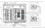
On the Electrolytic board, which test points get the black probe and which get positive? I originally just adjusted from stock down a couple points to 7.4mv, but now am wondering if I had it reversed and have my idle voltage set negative. The service manual illustration looks like its saying TP3 & TP4 are (+) and the center points are (-)
Here's a pic I took prior to making any adjustments: