• The move to the new server is done. There are some software and database maintenance updates in process. This has us passing the hat around to help out. We appreciate any donations. Seriously, even a dollar helps. The payment page may be found here - https://www.audiokarma.org/support.html

Yamaha A1 restoration 2021

Hifibythekg

Super Member
Hi all.
First question.
Want to discharge those two big caps before I touch anything...
Please can anyone tell me exactly how best I should perform this procedure? Apparently it was switched on in the last couple of CCDDE44C-2925-4785-B610-1542E2F258D1.jpeg days.
 
Register to hide this ad
the drain the cap instructions in the p2200 service manual say to use 100w 8ohm resistor to drain the caps. I just got some leads on the resistor and then touched them to the cap bolts. A smaller but larger resistance resistor would work, but you'd need to drain for longer. Don't know of any A1 service manuals online right now.

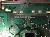
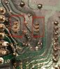
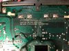
Yeah, those solder joints don't look nice. I'd clean off the flux and inspect further.
 

Attachments

  • 20210915_135231.jpg
    20210915_135231.jpg
    84.3 KB · Views: 45
  • 20210915_135237.jpg
    20210915_135237.jpg
    97.6 KB · Views: 42
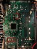
  • 20210915_134832.jpg
    20210915_134832.jpg
    83.6 KB · Views: 43
Hey Martin, thanks for your help.
When you say ‘cap bolts’ can you add a bit more detail, or describe it another way.
(I’m sure that any experienced repairers reading this must think I’m...)
 
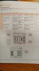
Would there be contact points above the text in this photo?
Could one just place a resistor across each of these pair of contacts?
And is there a function for those two holes below the centre of each pair of solder contacts?index.jpg ?
 
Hey Martin, thanks for your help.
When you say ‘cap bolts’ can you add a bit more detail, or describe it another way.
(I’m sure that any experienced repairers reading this must think I’m...)
Sorry, the p2200 main caps are bolted in. They're also the leads. You'd use an appropriate resistor and leads and touch them to the indicated solder pads you showed. You can use a multimeter to check them for voltage first.
 
Without having one to hand is there another workaround?
A couple of 10W 8ohm resistors soldered in parallel for longer..?

You could try a 1meg resistor and just not be in a hurry. Have you got a DMM with alligator clip leads? You could monitor the Volts while draining the caps.

*>[do not be in a rush]<*
 
you could use the alligator dmm leads to hold the resistor while you drain the caps while watching the voltage. Too small a resistor might go *poof*
 
so, set my DMM to Volts at say 200?
Then attach leads to the left hand solder pad.
See what it reads.
Then, put an appropriate resistor across those solder pads, yes?
 
They're what, 63V caps? Yeah. I have no idea how long it will take to drain down to the millivolt range using a 1meg resistor.
I was suggesting holding the resistor with the alligator probes and then hold the alligator probes against the solder pads, making sure you don't slip and short anything.
 
Last edited:
Back
Top Bottom