• The move to the new server is done. There are some software and database maintenance updates in process. This has us passing the hat around to help out. We appreciate any donations. Seriously, even a dollar helps. The payment page may be found here - https://www.audiokarma.org/support.html

Yamaha C-80 lost sound switching inputs

Not sure I could make that work
I was just being funny.. If GP would custom make it for your app. It might cost in excess of $500. If they could/would even do it. :dunno: Would need and inner and outer shaft.

The C-40, C-60/65, C-80/85 all share the same control. :thumbsup:
 
Last edited:
I’d assemble everything and try it once before any further drastic measures. Also, you should measure any resistance through the connected leads only and not directly from the resistive pads themselves … I think you know that already.
On the two outer connected leads it measures between 47-48kohms which is within about 20% tolerance. Putting one of the leads on the middle lead and rotating the wiper I only get a reading if I rotate the wiper all the way in one direction or the other so the metal contact part of the wiper is touch the upper part of the outermost lead where it connects to the wafer and there it reads the full resistance on both sides. I don't get a reading anywhere in the middle of the wafer and I think the photo above shows why. This is the case even when I just assemble one wafer and wiper and squeeze them together with my fingers.

Then if I put say the black alligator clip lead for the meter on an outer leg and touch the red tipped lead of the meter anywhere in the center of the wafer - nothing. Reads OL.

I just think the wafer is toast. I'm new at this I could be wrong but this seems like solid evidence.
 
On the two outer connected leads it measures between 47-48kohms which is within about 20% tolerance. Putting one of the leads on the middle lead and rotating the wiper I only get a reading if I rotate the wiper all the way in one direction or the other so the metal contact part of the wiper is touch the upper part of the outermost lead where it connects to the wafer and there it reads the full resistance on both sides. I don't get a reading anywhere in the middle of the wafer and I think the photo above shows why. This is the case even when I just assemble one wafer and wiper and squeeze them together with my fingers.

Then if I put say the black alligator clip lead for the meter on an outer leg and touch the red tipped lead of the meter anywhere in the center of the wafer - nothing. Reads OL.

I just think the wafer is toast. I'm new at this I could be wrong but this seems like solid evidence.
You may well be right. The 47-48kΩ is typical for 50K volumes. Time to order replacements. Remember that you’ll have to replace the wafers in both channels and not only the one that’s broken.

I‘d still reassemble and test while waiting for new ones. Did the loudness work before opening the unit?
 
You may well be right. The 47-48kΩ is typical for 50K volumes. Time to order replacements. Remember that you’ll have to replace the wafers in both channels and not only the one that’s broken.

I‘d still reassemble and test while waiting for new ones. Did the loudness work before opening the unit?
It would work until I turned it down about 20% of the way and then would cut out. It was noisy too. Volume was noisy too.
 
Ok the replacement pot arrived. I've soldered it in and it works better than the original one. Getting some pops when I use it so going to look at the coupling caps in the volume and loudness circuit and check my solder joints
 
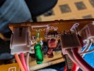
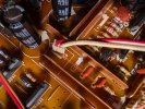
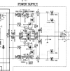
Ok my replacement volume/loudness pot is working correctly and maybe the original did too - by almost dumb luck I have discovered this. As with the original pot the loudness would cut out after turning it down about 25%. I unsoldered the connector for the cable in the photos below to get some slack to put the volume/loudness circuit board and then tried the unit with that cable unsoldered. Loudness works perfectly this way. Problem is I am having a hard time determining what this cable connects to the other side (also pictured below). It's close to the power supply circuit and parametric eq circuit. Doesn't seem like it could be power though because how would a volume pot work at all if it's not getting voltage. Not sure though
 

Attachments

  • Untitled 2.jpg
    Untitled 2.jpg
    183.1 KB · Views: 10
  • PXL_20241115_045838027.jpg
    PXL_20241115_045838027.jpg
    91.7 KB · Views: 10
  • PXL_20241115_045904891.jpg
    PXL_20241115_045904891.jpg
    147.7 KB · Views: 10
hmm time to check caps in the power supply I would guess then. Still doesn't make sense how the volume could work if the cable connecting to the power supply is disconnected.
 
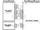
Looks like it connects tone control 1 board to tone control 2 board. What’s the voltage on the red cable, if any? Maybe it’s not power …

A0F4BB76-9DE7-4767-9F19-D3B8F501AF00.jpeg
 
Back
Top Bottom