• The move to the new server is done. There are some software and database maintenance updates in process. This has us passing the hat around to help out. We appreciate any donations. Seriously, even a dollar helps. The payment page may be found here - https://www.audiokarma.org/support.html

Yamaha CA-1000/CA1000II Power Supply and Protection Circuit Diagnostics, & Lower SNR values with the QA403

In regard to your heat test by touch:
Review findings: There is broad agreement between in vitro and in vivo studies for superficial burns. There is clear evidence that the perception of pain in adult human skin occurs just above 43°C. When the basal layer of the epidermis reaches 44°C, burn injury occurs. For superficial dermal burns, the rate of tissue damage increases logarithmically with a linear increase in temperature. Beyond 70°C, rate of damage is so rapid that interpretation can be difficult. Depth of injury is also influenced by skin thickness, blood flow and cooling after injury. There is less clinical evidence for a time-temperature relationship for deep or subdermal burns. Bioheat transfer models are useful in research and becoming increasingly sophisticated but currently have limited practical use. Time-temperature relationships have not been established for burns in children's skin, although standards for domestic hot water suggest that the maximum temperature should be revised downward by 3-4°C to provide adequate burn protection for children.
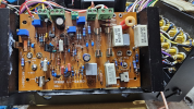
 
I am seeing the right channel at 70C and the left channel at 47C in Class A.
Measure voltages between TP3 & TP4 to confirm correct bias current. Do this when one side is significantly cooler thay the other, as per the quote. There was a recent thread where one channel was operating in AB despite operations switch set to class A.
 
Right side bias Class A was running high @1.24vdc
Adjusted all settings on left and right
Both are now at 60C
Unsure of why these have changed with very little run time on the unit
 
Brain teaser:
Remove TR611
Remove R633
Measure from R629 @ the connection point of R633 to ground with ohm meter and receiving 0.00ohms
R629 measures 680ohms
R623 measures 3.3k ohms
I am not finding a path in the circuit that would create this short to ground. Any assistance would appreciated.
Thank you
 
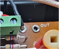
Pull the black E wire next to the OUT pin and remeasure, short "fixed" would indicate a solder bridge or similiar underneath TR611 socket
 
Pull the black E wire next to the OUT pin and remeasure, short "fixed" would indicate a solder bridge or similiar underneath TR611 socket
I did get this short to clear without a reasonable explanation.

Now I still have +28vdc at the OUT/E
Doesn't blow fuses
Relay is turning on
DBT is working correctly
Primary stage differential amplification circuit adjust easily to 15v
Mid-Point Potential Adjustment is @+28v

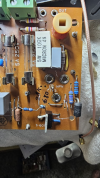
1728417589017.png

1728417948368.png

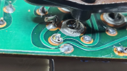
These next two photos were taken yesterday when I had the short

1728417685814.png

1728417733869.png
 
Last edited:
Short possibly due to solder splatter shorting out tracks in red circle, maybe add some non conductive "paint"

Now I still have +28vdc at the OUT/E
Doesn't blow fuses
Relay is turning on

You have 2 faults, +28Vdc at OUT and that the relay is turning on when +28Vdc at OUT.
28V will damage some (high spl) speakers and make an almighty (~100W) noise on others. Do not connect spkrs until issue cleared.

edit pix shows various parts lifted(to track down the short), suggest you reconnect/normalize the amp then troubleshoot the +28Vdc issue
 

Attachments

  • CA1000short.jpg
    CA1000short.jpg
    233.6 KB · Views: 5
Short possibly due to solder splatter shorting out tracks in red circle, maybe add some non conductive "paint"


You have 2 faults, +28Vdc at OUT and that the relay is turning on when +28Vdc at OUT.
28V will damage some (high spl) speakers and make an almighty (~100W) noise on others. Do not connect spkrs until issue cleared.

edit pix shows various parts lifted(to track down the short), suggest you reconnect/normalize the amp then troubleshoot the +28Vdc issue
I sure don't see it

1728421092283.png
 
I sure don't see it
Because the fault has cleared. The supplied pix show solder splatter in the vicinity (see pix) need to clean boards with a soft brush.

Since the OUT is not connected past the AMP board, would that not be the reason the relay is not seeing it?
Again, you have the amp in an unkown(to me) state so I wont waste my time trying to troubleshoot in this state. Yes I understand that parts were disconnected to track down the short. Yes a disconnected OUT pin would explain why the relay still kicks in. I'd be happier if you reconnected everything up, leaving OUT disconnected then remeasure at OUT.
 
Post #286 first photo is exactly what you have requested "
You understand that I'm not sitting in front of the unit, so when I see post #286 last (most recent?) photo I think "Dogs Breakfast", don't waste my time

I'd be happier if you reconnected everything up, leaving OUT disconnected then remeasure at OUT.
You didn't bother measuring...
 
You understand that I'm not sitting in front of the unit, so when I see post #286 last (most recent?) photo I think "Dogs Breakfast", don't waste my time


You didn't bother measuring...
That is exactly what I provided. I am sorry I was not more clear.
 
You understand that I'm not sitting in front of the unit, so when I see post #286 last (most recent?) photo I think "Dogs Breakfast", don't waste my time


You didn't bother measuring...

Now I still have +28vdc at the OUT/E
Doesn't blow fuses
Relay is turning on
DBT is working correctly
Primary stage differential amplification circuit adjust easily to 15v
Mid-Point Potential Adjustment is @+28v
 
You understand that I'm not sitting in front of the unit, so when I see post #286 last (most recent?) photo I think "Dogs Breakfast", don't waste my time


You didn't bother measuring...
I thought the photo clearly showed that all parts had been reinstalled and that the OUT and associated e was not connected. How should I have described?
 
As of this very moment in time:

I have +48vdc at the OUT/E The item that changed this value is connection of E at the OUT
Doesn't blow fuses
Relay is turning on
DBT is working correctly
Primary stage differential amplification circuit adjust easily to 15v
Mid-Point Potential Adjustment is @+48V

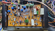
1728482159579.png
 
So what is your take on the above voltage measurements?
When current flows through a transistor b-e junction there will be a 0.6V drop in the direction of the arrow.

Problem is evident at the OUT pin, close enough to TR611e.
TR611 Vbe is ok, problem is Vb is too high, so from TR611's point of view, bs in, bs out.
Likewise TR609 Vbe and Vb again too high.
Note the problem is coming from the +50 regulated supply not the +B unregulated supply.

Working back, TR606 Vc is again way too high, Also note TR606 Vc > TR609 Vb > TR609 Ve > TR611 Ve all by a reasonable/expected Vbe...

TR606 Vc is high because of very low current flow through R613,4,5 so the corresponding I x R volt drop is low.

So where should this current be flowing? My take is down the path TR606c-e, R620, TR605.
So if R620 is open (unlikely) there would be no current flow, anyway TR605 Vc indicates R620 not open.
Also if TR605 has failed or is off then again no current flow.
So the questions become,
Has TR605 failed?
Who controls TR605

Point to the above, rather than just posting voltages, diy your own analysis and post what you think is happening, sure we get it wrong some times but that's how we learn rather than being spoon fed...
 
Back
Top Bottom