• The move to the new server is done. There are some software and database maintenance updates in process. This has us passing the hat around to help out. We appreciate any donations. Seriously, even a dollar helps. The payment page may be found here - https://www.audiokarma.org/support.html

Yamaha CA 600 Repair 2026

Some vintage shops do that for a reason, the broken stuff that people bring to them sometimes
get sold to them . It's their source for vintage gear. And the profit is much larger
possibly selling gear they bought broken at a very low price , than fixing it for someone.
 
I would like to learn more about the hobby. I learn fast and I can do anything mechanical.
being mentored and mentoring requires a strong connection between individuals. you can't just expect to walk in off the streets and say "mentor me" nor could i just walk into an autobody class and pick someone to mentor.

i've been on both ends and mentoring someone is not easy.
 
But thats BS, you want to sell vintage electronics but when it comes to repair it's Too Bad So Sad??? I am by no means even close to an expert but I would like to learn more about the hobby. I learn fast and I can do anything mechanical. I retired at 55 and for the past 7 years I have been restoring and repairing cars and motorcycles and vintage electronics and anything around the house that needs it but diagnosing electronics is damn near kicking my ass. Who is going to repair this stuff in 20 years. There is not one single repair shop in Des Moines Iowa and we are talking almost 2 million people here and the surrounding communities.

There are plenty of teaching tools online and not hard to find. Start with the basics then proceed from there. Have patience and expect to make mistakes.

When I was in ET school I thought I had everything down pat. Went to test out only to find I had nearly all of the questions wrong in a certain area. The fella giving the test said he never saw anything like this, then asked me a question pertaining to that subject. I had it backwards. Took the test again and passed.
 
New FR's are here and installed.

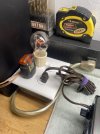
Plugged into DBT and it lights up just a little.

Too afraid to plug it into the wall outlet.

Relay still not engaging.
 

Attachments

  • b18e8289-abbd-424a-a7e5-bdb8575ed92d.jpg
    b18e8289-abbd-424a-a7e5-bdb8575ed92d.jpg
    98.2 KB · Views: 6
  • 788c1b52-cbf6-440e-9332-38cb59ec3d86.jpg
    788c1b52-cbf6-440e-9332-38cb59ec3d86.jpg
    120.3 KB · Views: 6
  • b8a44343-a40b-40d2-8414-92a14037937f.jpg
    b8a44343-a40b-40d2-8414-92a14037937f.jpg
    122.3 KB · Views: 6
Back off the bias to a few mV or even 0mV then power up without DBT then readjust bias and offset then have a listen
Do the above again , do this on DBT, then after go to wall outlet and reset per the SM.

But first see if you have the right voltages on the PS board.
New FR's are here and installed.

Plugged into DBT and it lights up just a little.

Too afraid to plug it into the wall outlet.

Relay still not engaging.
What size bulb is that? I think the brightness is low according to your pic.

You should be ok.


Going out for a few hours. maybe some one else will give additional advice .

Athanasios
 
  • Like
Reactions: mbz
What Nashou66 said. While on DBT set bias to zero abouts.

Basic health check of power supply, expect voltages to be 50-70% of expected voltages, this is why the relay does not click.

The power up on mains, not DBT, expect relay to click after 4 or so seconds.
If relay does not click then recheck power supply voltages, eg,B+, and unregulated supply at main filter caps.

If relay did click then set bias as per sm
 
check dc offset once more while still on the dim bulb just to make sure.

obviously , you won't get a measurement at the speaker output because the relay is open. you will need to check at output of amp or input of relay
 
Do the above again , do this on DBT, then after go to wall outlet and reset per the SM.

But first see if you have the right voltages on the PS board.
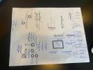
I checked all the PSB voltages and wrote them down on the first picture. This is on the DBT.

I reset Midpoint and Bias on both boards as close to Zero as possible because it is easier than finding 47 MV. Again on the DBT.

The DBT is not glowing at all. Relay still not clicking.


What size bulb is that? I think the brightness is low according to your pic.

It should be 60 watt.

I did all the above before I got the two latest messages from MBZ and Painttoad.
 

Attachments

  • 6d8f2d12-c8f2-4e21-8069-8e660e509c65.jpg
    6d8f2d12-c8f2-4e21-8069-8e660e509c65.jpg
    110.2 KB · Views: 7
Last edited:
Plugged the amp directly into a wall socket and the Relay is still not clicking, still not moving. Again I checked the relay with a good new 9 volt battery and she clicks just perfect.

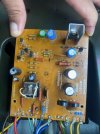
I retook the PSB voltages readings and here is what I got.

YE 31
Black 0
B+ 0
BE -,2
PL 4.7
LO .009
L -.005
R .08
RO 0
LH .008
RH .004

Rechecked MidPoint and Bias and the left side was still at Zero and Zero. Right side barely needed a little tweaking but is at Zero and Zero.

Took voltage readings at the Main Filter Capacitor Board.

ET 0
B+ 39.2 Vdc
AC 28.5 Vac
B- -39.1
ES 0
E 0

Still no click at the Relay.
 

Attachments

  • 220f04e6-5c24-45a9-a232-922436e3967e.jpg
    220f04e6-5c24-45a9-a232-922436e3967e.jpg
    102.6 KB · Views: 3
  • b72501dc-6e4c-4335-bd93-905057cc0836.jpg
    b72501dc-6e4c-4335-bd93-905057cc0836.jpg
    113.1 KB · Views: 3
Last edited:
L -.005
R .08
What scale did you take measurements on? 2V scale?
Assume L is .005V/5mV which is very good
R at 0.08/80mV is too high but not that high to cause protection issue.

You probably have a fault in the protect circuit.
Plz measure dc voltage at the following points, black MM probe connected to any black speaker connector/post.
See attached
1. R708, expect +0.6V
2. Jumper J702, +20V
3 TR704e +12V
4 R710/TR704b +11.4V
5 R716 0V

Also post new pix of power supply board, both components and solder side.
 

Attachments

  • CA600_psu.pdf.png
    CA600_psu.pdf.png
    470.1 KB · Views: 49
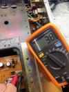
What scale did you take measurements on? 2V scale.
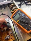
I am using the Yellow meter which is Auto Scaling but has a separate setting for mV. I am using the Volts DC scale see photo below measuring #5 R716
Plz measure dc voltage at the following points, black MM probe connected to any speaker black.
1. R708, expect +0.6V Zero
2. Jumper J702, +20V Zero
3 TR704e +12V 15.1 Vdc
4 R710/TR704b +11.4V 14.5 Vdc
5 R716 0V 0.006 Vdc
Also post new pix of power supply board, both components and solder side.
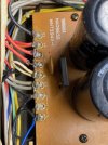
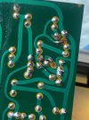
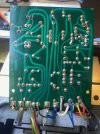
Yes I know the soldering looks like **** but I assure you I double and triple checked all the connections with the MultiMeter. All the above was done plugged into wall outlet.
 

Attachments

  • 8a0fce64-57cb-4ddd-93bd-49e02a500830.jpg
    8a0fce64-57cb-4ddd-93bd-49e02a500830.jpg
    101.4 KB · Views: 9
  • 9880aa0a-1788-4f91-9257-f9842d279ad5.jpg
    9880aa0a-1788-4f91-9257-f9842d279ad5.jpg
    129.3 KB · Views: 11
  • dee0753d-3ce4-488c-8101-b1a585465f43.jpg
    dee0753d-3ce4-488c-8101-b1a585465f43.jpg
    113.2 KB · Views: 10
  • a6b904a2-5153-41e4-9730-530cd8dde556.jpg
    a6b904a2-5153-41e4-9730-530cd8dde556.jpg
    77 KB · Views: 10
Last edited:
  • Like
Reactions: mbz
Measure the voltage DC at the Anode of D706
and at either side of FR703 .
The following readings were taken with Amp plugged into wall outlet and amp turned on.
D706 at the anode 0 at the Cathode 0
D705 at the anode 0 at the Cathode 0.172

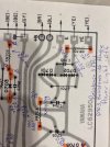
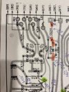
FR703 is brand new and is reading 0.185 Vdc at the left end and 76 Vdc at the right end. See pic for reference. Got the same readings with power off.
 

Attachments

  • 85182cbf-4ca9-47ff-908b-d4ad35debfca.jpg
    85182cbf-4ca9-47ff-908b-d4ad35debfca.jpg
    82 KB · Views: 5
The following readings were taken with Amp plugged into wall outlet and amp turned on.
D706 at the anode 0 at the Cathode 0
D705 at the anode 0 at the Cathode 0.172

FR703 is brand new and is reading 0.185 Vdc at the left end and 76 Vdc at the right end. See pic for reference. Got the same readings with power off.
Zero volts on the cathode side of D706 cannot be true if you had +20 volts on J702. Are you using DC scale?

Also Is FR703 new? With power off measure it resistance.
ca600_psu-pdf-png.3847810
 
  • Like
Reactions: mbz
1. R708, expect +0.6V Zero
2. Jumper J702, +20V Zero
Looks like we are back to blown fusibles FR701,2 or...
Point 2 above is D706 cathode, "must" be +20Vdc

Candidates are blown FR701 or FR702 or zener D705 open.

Start by again resistance measurement of FR701 and FR702, measure in-circuit, expect OL
 
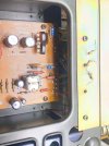
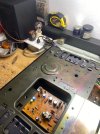
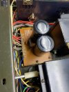
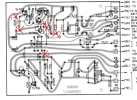
Here all the you asked for and more.

Large schematic maybe hard to read so I blew it up into 4 quarters.

The amps power light is not coming on anymore.
 

Attachments

  • e0b7f044-8f52-430b-bd90-56d8c6bfa552.jpg
    e0b7f044-8f52-430b-bd90-56d8c6bfa552.jpg
    122.4 KB · Views: 6
  • b35fd3eb-59fe-48af-906f-fd26ac442844.jpg
    b35fd3eb-59fe-48af-906f-fd26ac442844.jpg
    118.1 KB · Views: 7
  • 92080450-cc31-4f18-94e9-444f2eebbdb2.jpg
    92080450-cc31-4f18-94e9-444f2eebbdb2.jpg
    118 KB · Views: 9
  • 5859dfb6-dd33-4f82-be03-65e07f4aa65a.jpg
    5859dfb6-dd33-4f82-be03-65e07f4aa65a.jpg
    129 KB · Views: 9
  • 3d39ef5b-0f2f-445a-a57d-81809b2f1a9e.jpg
    3d39ef5b-0f2f-445a-a57d-81809b2f1a9e.jpg
    123 KB · Views: 6
  • 2e556bc8-3339-4cf9-a73e-0f423eb6b24c.jpg
    2e556bc8-3339-4cf9-a73e-0f423eb6b24c.jpg
    116 KB · Views: 5
  • f30b4994-79c1-46b6-9559-e9121e5af318.jpg
    f30b4994-79c1-46b6-9559-e9121e5af318.jpg
    123.3 KB · Views: 5
Post #211 pix 2 appears to show a 47ohm resistor at FR702, sm calls for 3.9ohms?
Was there a 47ohm there originally? Part number suggests so.
 
Last edited:
From post #175 The pic below is from the Service Manual

I forgot to write on the previous post the resistance of FR703. I could not get a reading, it just bounces all over the place and will not stabilize.

1790539795669.png


FR701 says HW403390 at its base on the board so I put a 3.9 ohm resistor in.
FR702 says HW403390 at its base on the board so I put a 3.9 ohm resistor in.
FR703 says HW404470 at its base on the board so I put a 47 ohm resistor in.

What did I do wrong?
 
Last edited:
I forgot to write on the previous post the resistance of FR703. I could not get a reading, it just bounces all over the place and will not stabilize.
Do you have a replacement, yeah it's probably 47ohms, same as CA800 and CA1000, replace with a 47ohm then DBT then measure voltage drop across FR703 so we can calculate current flow. I will do a search on whether it should be 3.9 or 47ohms...

edit page 14 of sm has that FR listed as FR701, 47ohms, 100mA
 
Last edited:
Do you have a replacement, yeah it's probably 47ohms, same as CA800 and CA1000, replace with a 47ohm then DBT then measure voltage drop across FR703 so we can calculate current flow. I will do a search on whether it should be 3.9 or 47ohms...

edit page 14 of sm has that FR listed as FR701, 47ohms, 100mA
Yes I bought extras and can replace FR703 but I don't think I should do anything yet.

You are saying FR701 is 47 ohm but I have a 3.9 ohm in the FR701 spot. I am confused

Please advise of what goes in the following spots.

FR701
FR702
FR703

???
 
Back
Top Bottom