

You are using an out of date browser. It may not display this or other websites correctly.
You should upgrade or use an alternative browser.
You should upgrade or use an alternative browser.
Yamaha CA 600 Repair 2026
- Thread starter PioneerPro
- Start date

Those are not schematics, they are board layouts.Here all the you asked for and more.
Large schematic maybe hard to read so I blew it up into 4 quarters.
The amps power light is not coming on anymore.
The schematics make it easier to trace connections v s layouts which dont show traces.
Try to use those for making notes etc.
Sorry, just a pet peeve of mine

Athanasios
Last edited:

schematic is page 20 in the service manual.Here all the you asked for and more.
Large schematic maybe hard to read so I blew it up into 4 quarters.
The amps power light is not coming on anymore.
The 2 sections we need to look atschematic is page 20 in the service manual.


Athanasios
PioneerPro
Active Member
OK everybody thank you for showing me that you have bigger penises than me.dbt power up and measure volt drop across FR703, about 4Vdc?
Now can we get back to this damn amp?
I powered up the amp on DBT and measured voltage at one end of FR703. It did not bounce around however I am getting two different readings depending on which end of FR 703 I measure at. Please see pics. 13.7 Vdc at the left end and 72.3 Vdc at the right end.
Attachments


Is that with the 47 ohm resistor in its place or the 3.9 ohm resistor?OK everybody thank you for showing me that you have bigger penises than me.
Now can we get back to this damn amp?
I powered up the amp on DBT and measured voltage at one end of FR703. It did not bounce around however I am getting two different readings depending on which end of FR 703 I measure at. Please see pics. 13.7 Vdc at the left end and 72.3 Vdc at the right end.
If its the 47 ohm that seems too high a voltage drop, @mbz said it should be about 4 VDC , you have 58.68 VDC drop.
If my math is correct , With a 47 ohm resistor that would be 58.68 vdc/47 ohms, which come to 1.25 amps I=V/R , Not sure but that seems too high.
if its the 3.9 resistor then the current through it will be much higher and probably burn it out if left on too long.
Athanasios
PioneerPro
Active Member
Yes, FR703 is a 47ohm resistor like the Service Manual Says it is supposed to be. I have not replaced anything because no one told me to. MBZ mentioned it in Post 219 and I replied and nothing else was said about it replacing it because I thought he made a mistake, but maybe it was me that did not understand clearly.Is that with the 47 ohm resistor in its place or the 3.9 ohm resistor?
If its the 47 ohm that seems too high a voltage drop, @mbz said it should be about 4 VDC , you have 58.68 VDC drop.
If my math is correct , With a 47 ohm resistor that would be 58.68 vdc/47 ohms, which come to 1.25 amps I=V/R , Not sure but that seems too high.
if its the 3.9 resistor then the current through it will be much higher and probably burn it out if left on too long.
Please reference my #218 post and get back to me.
DBT should be lit up like a christmas tree.I powered up the amp on DBT and measured voltage at one end of FR703. It did not bounce around however I am getting two different readings depending on which end of FR 703 I measure at. Please see pics. 13.7 Vdc at the left end and 72.3 Vdc at the right end.
Would have preferred that you clipped probes across each side of FR703 rather than measuring to GND but not an issue in this case. Normal current is about 100mA. You have a near short somewhere which explains why you keep blowing the FR's.
For me, the next step would be to disconnect load from the power supply to identify the problem area (Tone, filter, function board or power supply or protect circuit)
Suggests unsolder/disconnect the brown B+ wire on the power supply/relay board (red cross) then DBT power up and recheck FR703 voltages. With B+ disconnected both the power supply and protect circuits are operational
Attachments

Assuming above test is ok, both sides of FR703 measure about 73Vdc.
Next step would be to reconnect B+ on power supply board then disconnect the brown B+ wire on the tone board and repeat FR703 voltage measurements.
edit keep in mind that the brown wire is hot, do not let it short on the board/chassis/etc
Next step would be to reconnect B+ on power supply board then disconnect the brown B+ wire on the tone board and repeat FR703 voltage measurements.
edit keep in mind that the brown wire is hot, do not let it short on the board/chassis/etc
Attachments

Last edited:
@mbz , shouldn't he also measure the resistance of FR703 to make sure it didn't change after being stressed by the 1.25 amps before anything else?
@PioneerPro , measure the resistance of FR703 to make sure it didn't go high .
Also show the package from mouser/digikey just incase you ordered 47k resistors.
Athanasios
@PioneerPro , measure the resistance of FR703 to make sure it didn't go high .
Also show the package from mouser/digikey just incase you ordered 47k resistors.
Athanasios
Yeah, should be done.shouldn't he also measure the resistance of FR703 to make sure it didn't change after being stressed by the 1.25 amps before anything else?
TBH I'm sceptical of those voltage measurements, that's why I preferred measuring actual volt drop.
1.25A/73W would have vapourised that 100mA/0.5W resistor, especially considering time to take measurements.
PioneerPro
Active Member
See post #177Also show the package from mouser/digikey just incase you ordered 47k resistors.
It is what Nashou66 told me to order.
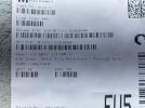
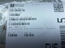
Please advise if these are correct?????????????????????????????????????????????????????????????
Attachments
Last edited:
PioneerPro
Active Member
It did not light up then.DBT should be lit up like a christmas tree.
Got around 60 Vdc when probes at both ends of FR703Would have preferred that you clipped probes across each side of FR703 rather than measuring to GND but not an issue in this case. Normal current is about 100mA. You have a near short somewhere which explains why you keep blowing the FR's.
Disconnected Brown B+ wire at the PSB and still got the same readings at FR703 60VdcFor me, the next step would be to disconnect load from the power supply to identify the problem area (Tone, filter, function board or power supply or protect circuit)
Disconnected Brown B+ wire at the Tone Board and got the same reading at FR703 60Vdc
Disconnected Brown B+ wire at the Filter Board and got the same reading at FR703 60Vdc
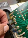
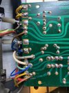
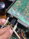
Disconnected Brown B+ wire at the Function Board and got 0.30 Vdc at the left end and 1.72Vdc at the right end. When I placed both probes on both ends of FR730 the readings just bounced all over the place. Please look at the pic #4 an make sure I got this one right. Could not find any brown wire except in the 4 wire plug.
The voltage was the same with the brown wire disconnected and wrapped with black tape at the PSB.Assuming above test is ok, both sides of FR703 measure about 73Vdc.
Next step would be to reconnect B+ on power supply board then disconnect the brown B+ wire on the tone board and repeat FR703 voltage measurements.
edit keep in mind that the brown wire is hot, do not let it short on the board/chassis/etc
Note FR703 resistance at this time is All Over The Place. Meter starts in K then goes to M resistance readings.
I think you guys are trying to kill me.
Attachments


Sparkplug
Super Member
DBT should be lit up like a christmas tree.

FR703 needs to be 47ohms 0.5W.Please advise if these are correct
I could not find the part number at mouser AU (will try USA later)
Indicates FR703 has failed. Possibly you are using a 0.25W part??? that blows instantly. Probably also explains why DBT is not lit up?Note FR703 resistance at this time is All Over The Place. Meter starts in K then goes to M resistance readings.
I need to check if that 47R is ok
edit
Mouser 279-FRN25J47R is marked EOL and also 0.25W however this might be a mouser error. I could not find FRN in the new manufacturers data sheet so can't confirm.
On your next mouser order get some
594-NFR25H0004709JR5
yeah, a little expensive but they are fusible and flameproof
Last edited:
ok you did this , but you got the same results with 73 on one side and 13 on other correct?DBT should be lit up like a christmas tree.
Would have preferred that you clipped probes across each side of FR703 rather than measuring to GND but not an issue in this case. Normal current is about 100mA. You have a near short somewhere which explains why you keep blowing the FR's.
For me, the next step would be to disconnect load from the power supply to identify the problem area (Tone, filter, function board or power supply or protect circuit)
Suggests unsolder/disconnect the brown B+ wire on the power supply/relay board (red cross) then DBT power up and recheck FR703 voltages. With B+ disconnected both the power supply and protect circuits are operational
If yes then you should have stoped there because mbz said this next ( bold test below)
Assuming above test is ok, both sides of FR703 measure about 73Vdc.
Next step would be to reconnect B+ on power supply board then disconnect the brown B+ wire on the tone board and repeat FR703 voltage measurements.
edit keep in mind that the brown wire is hot, do not let it short on the board/chassis/etc
This was not 73 on either side as you stated here below
and here the resistance should measure 47 ohms with power off( always measure resistance with power off) and one leg liftedIt did not light up then.
Got around 60 Vdc when probes at both ends of FR703
Disconnected Brown B+ wire at the PSB and still got the same readings at FR703 60Vdc
Disconnected Brown B+ wire at the Tone Board and got the same reading at FR703 60Vdc
Disconnected Brown B+ wire at the Filter Board and got the same reading at FR703 60Vdc
Disconnected Brown B+ wire at the Function Board and got 0.30 Vdc at the left end and 1.72Vdc at the right end. When I placed both probes on both ends of FR730 the readings just bounced all over the place. Please look at the pic #4 an make sure I got this one right. Could not find any brown wire except in the 4 wire plug.
The voltage was the same with the brown wire disconnected and wrapped with black tape at the PSB.
Note FR703 resistance at this time is All Over The Place. Meter starts in K then goes to M resistance readings.
I think you guys are trying to kill me.
Id start with putting a new 47 ohm resistor in FR703 .
Crap it is a 1/4 watt part !! My Bad !!FR703 needs to be 47ohms 0.5W.
I could not find the part number at mouser AU (will try USA later)
Indicates FR703 has failed. Possibly you are using a 0.25W part??? that blows instantly. Probably also explains why DBT is not lit up?
I need to check if that 47R is ok

But if earlier you said the voltage drop should be 4 VDC the amps across it would be 4/47=0.0851, should that be enough ?
EDIT : Ohhhh I was thinking Current , Watts would be .0851x4= .3404 Watts which is too high .
Nashou
Last edited:
"Good idea Lord" (apology to python)You have 2 100 ohm 1/4 watt resistors which you could parallel to get a 50 ohm 1/2 watt equivalent for test ing in FR703 for now.
Go with 2 x 100ohm in parallel then DBT power up then power down and recheck if FR703 survived.
Do you have a 60-75W bulb for DBT?
If FR703 survived then disconnect brown B+ wire from power supply board then recheck voltages across FR703.
PioneerPro
Active Member
No one is reading what I have been writing for the past 2 pages of this thread. People are skimming and missing a lot. You guys are asking questions that I have already answered and too all over the place. This has become one huge complicated mess to me and once again I have no training in electronics repair.
When I was younger I never could understand what, Too Many Cooks Spoil The Broth meant.
I am ignoring everything after my post #233 because it is just a confusing mess to me.
Did anyone notice that when I disconnected the Brown B+ wire at the Function Board the huge variance in the FR703 measurements compared to the other boards? Is that not significant??????????????
Please clearly explain how you want me to continue?
PS - I do not know what PARALLEL TWO RESISTORS means.
When I was younger I never could understand what, Too Many Cooks Spoil The Broth meant.
I am ignoring everything after my post #233 because it is just a confusing mess to me.
Did anyone notice that when I disconnected the Brown B+ wire at the Function Board the huge variance in the FR703 measurements compared to the other boards? Is that not significant??????????????
Please clearly explain how you want me to continue?
PS - I do not know what PARALLEL TWO RESISTORS means.