• The move to the new server is done. There are some software and database maintenance updates in process. This has us passing the hat around to help out. We appreciate any donations. Seriously, even a dollar helps. The payment page may be found here - https://www.audiokarma.org/support.html

Yamaha CA 600 Repair 2026

No one is reading what I have been writing for the past 2 pages of this thread. People are skimming and missing a lot. You guys are asking questions that I have already answered and too all over the place. This has become one huge complicated mess to me and once again I have no training in electronics repair.

When I was younger I never could understand what, Too Many Cooks Spoil The Broth meant.

I am ignoring everything after my post #233 because it is just a confusing mess to me.

Did anyone notice that when I disconnected the Brown B+ wire at the Function Board the huge variance in the FR703 measurements compared to the other boards? Is that not significant??????????????

Please clearly explain how you want me to continue?

PS - I do not know what PARALLEL TWO RESISTORS means.
We went passed it cause you did the sequences wrong.

re read posts 228 through 231 carefully.

And post 326 where you should have stoped according to mb's previous posts

Look up Parallel resistors, Google is your friend ;)

Athanasios
 
Starting over right now at this point.

I removed the Brown wire from the PSB.

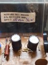
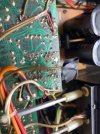
I ran two 100 ohm 1/4 watt resistors in Parallel and installed them. See Pic

I tested the resistors in the board with no power and got 48 ohm then when I swapped the MM leads I got 51 ohm.

I powered up the DBT and the amp and measured the FR703 resistors and got 0.251 Vdc with both probes on the resistor ends. I tested the two separate ends with the Negative Probe on the chassis and got 69 Vdc on the left and and 70 Vdc on the right end.

Brown wire is still disconnected. Please advise on how to proceed?
 

Attachments

  • 7555e86d-bcfc-44d0-9b9a-a8b08618635a.jpg
    7555e86d-bcfc-44d0-9b9a-a8b08618635a.jpg
    108 KB · Views: 6
  • c0ab0190-6f8d-456a-bda1-1479ca3eb468.jpg
    c0ab0190-6f8d-456a-bda1-1479ca3eb468.jpg
    131.7 KB · Views: 6
Starting over right now at this point.

I removed the Brown wire from the PSB.

I ran two 100 ohm 1/4 watt resistors in Parallel and installed them. See Pic

I tested the resistors in the board with no power and got 48 ohm then when I swapped the MM leads I got 51 ohm.

I powered up the DBT and the amp and measured the FR703 resistors and got 0.251 Vdc with both probes on the resistor ends. I tested the two separate ends with the Negative Probe on the chassis and got 69 Vdc on the left and and 70 Vdc on the right end.

Brown wire is still disconnected. Please advise on how to proceed?
Ok looks good, .251/48 ohms = .01 Amps

now do what @mbz said here ( 69 and 70 are close enough to 73) in that exact order.

Assuming above test is ok, both sides of FR703 measure about 73Vdc.
Next step would be to reconnect B+ on power supply board THEN disconnect the brown B+ wire on the TONE BOARD and repeat FR703 voltage measurements.

edit keep in mind that THE BROWN WIRE IS HOT, DO NOT LET IT SHORT ON THE BOARD/CHASSIS/ETC

post measurements
 
  • Like
Reactions: mbz
Reconnected PSB B+ brown and disconnected Tone Board Brown.

Powered up on DBT and got the same as the previous readings. 0.251 Vdc and 70 Vdc with negative probe on the Chassis.

Please Proceed.
 

Attachments

  • c8b24c80-1a45-4f5f-9409-35346d8be083.jpg
    c8b24c80-1a45-4f5f-9409-35346d8be083.jpg
    83.3 KB · Views: 1
Reconnected PSB B+ brown and disconnected Tone Board Brown.

Powered up on DBT and got the same as the previous readings. 0.251 Vdc and 70 Vdc with negative probe on the Chassis.

Please Proceed.
Was DBT bright or stayed Dim? Id guess Dim since current remained the same .

Also were all the other boards +B supplies were still connected?

Athanasios
 
  • Like
Reactions: mbz
Yes it was dim.

Only one I disconnected was the Tone Board Brown Wire when I took the last FR703 reading.

Please Proceed.
Hmm seems like nothing upstream with all board connected , minus the tone board.

Ok Now connect the tone board and watch the DBT while also monitoring the measurement of voltage across RF703 in the same manner you measured the .251 VDC .

If DBT stays Bright and/or the voltage increases across FR703 shut it down , it means there is an issue most likely on the tone board.

Athanasios
 
  • Like
Reactions: mbz
I connected the MM to FR703 and turned on the DBT and turned on the AMP power and heard a click.

I checked and the relay was engaged. The Brown Tone Wire is disconnected.

Should I reconnect it?
 
Last edited:
  • Like
Reactions: mbz
Sorry need more detail.

Connect Brown wire back to Tone Board and watch DBT as I am connecting the wire? And as I am measuring voltage at FR703?
With power off reconnect B+ to tone board.

Now power up on DBT while having the MM clipped to both side of FR703 like you did earlier to get the .251 VDC voltage reading.
watch that voltage and also pay attention to the DBT to see if it goes bright and stays there. if it stays bright or the voltage reading goes higher by a lot across FR703 shut down power .
 
  • Like
Reactions: mbz
With power off reconnect B+ to tone board.

Now power up on DBT while having the MM clipped to both side of FR703 like you did earlier to get the .251 VDC voltage reading.
watch that voltage and also pay attention to the DBT to see if it goes bright and stays there. if it stays bright or the voltage reading goes higher by a lot across FR703 shut down power .
Did all this and the DBT barely blinked then went very dim. The relay is still clicking. The MM read 0.251 Vdc and stayed there.

Now what?
 
Did all this and the DBT barely blinked then went very dim. The relay is still clicking. The MM read 0.251 Vdc and stayed there.

Now what?
Now let's go to full power and see if relay clicks .

I would also have a different MM set up to adjust the bias , I assume it's set up to be at 0 from earlier on in the thread .
Correct?

And also monitor the voltage across FR703 at the same time, so leave that MM in its place, you will need another MM to see what the Bias is and adjust it to the SM specs/

Fingers crossed !! :D
 
Did anyone notice that when I disconnected the Brown B+ wire at the Function Board the huge variance in the FR703 measurements compared to the other boards?
Yes and we also noticed the behaviour when the B+ was disconnected from the psu board, which was more significant. In any case, I did not ask you to pull that connector, did you notice that it includes a GND connector. I had planned on lifting R443 when we got to the function board.

I am ignoring everything after my post #233 because it is just a confusing mess to me.
OK

edit bugga, missed above posts...
 
Last edited:
got the same as the previous readings. 0.251 Vdc
I think you have a failed voltage regulator or...
With PSU B+ wire disconnected the only load is "leakage" current through zeners and for the protect circuit. 5mA does not seem unreasonable. However what is unexpected is after adding load (filter and function boards) by reconnecting B+/disconnecting tone board the current remains 5mA.

Measure Vdc at B+ wire/solder blob on psu board
 
Plugged the Amp into a wall outlet and powered on the MM connected to FR703 ends. It is now reading .351 Vdc.

Yes the relay is still clicking.

Checked left and right Bias readings and they are both showing 0mv.

I need to find another set of alligator clips to set on the second MM to readjust the Bias.
 
Found second set of alligator clips and checked the Bias's on both boards

Got the left set at 46mv and the right set at 44mv.

Relay is still clicking.
 
Back
Top Bottom