

You are using an out of date browser. It may not display this or other websites correctly.
You should upgrade or use an alternative browser.
You should upgrade or use an alternative browser.
Yamaha CR-1020 adjust idle current TP1 to TP 0 measures 0 mV on both amp boards but will not adjust
- Thread starter Hifibythekg
- Start date
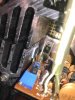

.9 Ω - .4 Ω = .5 emitter resistor is .47Ω close enough...0.4 ohms
Cant see the print or non-print side of the transistor. If these are improperly installed it would definitely impact your bias ( idle current )
Hifibythekg
Super Member
I didn't take a picture after installing but I'm pretty sure it's the right way around... I used a transistor tester to match up to the original BCE or whatever
I'm afraid it needs to be positively verified.I didn't take a picture after installing but I'm pretty sure it's the right way around... I used a transistor tester to match up to the original BCE or whatever
Hifibythekg
Super Member
Thanks Avionic.
I'll have to get back to you tomorrow if that's ok, will extract and check overnight.
Thanks, much appreciated!
I'll have to get back to you tomorrow if that's ok, will extract and check overnight.
Thanks, much appreciated!
Hifibythekg
Super Member
should the print side be touching the heatsink or the copper spring
Hifibythekg
Super Member
If you can tell me I'll get on with reversing them if required
Spring..should the print side be touching the heatsink or the copper spring
Hifibythekg
Super Member
If you can tell me I'll get on with reversing them if required
Hifibythekg
Super Member
KSA 1015 on both, print side facing up towards me
Hifibythekg
Super Member
Yes, print side is touching the spring.
What might be the next step?
What might be the next step?
What resistance value ?Trimpots were replaced with Bourn Multiturns
Sound quality ?Powers up relay clicks on and sound comes out fine.
Measuring between O and E will provide you with your DC offset..If the relay is "set".. Which has absolutely nothing to do with your bias trimmer.And will not respond to the trimmer adjustment.will do.
Just measured between O and E...
It gives 10 climbing 14 on the left.
But the right is at 27mV and doesn't respond to the Bourns being turned
Hifibythekg
Super Member
Thanks for the explanation.
Sound quality sounded fine.
Is 14 on one channel and 27 on the other an acceptable DC offset?
And what next to check?
Sound quality sounded fine.
Is 14 on one channel and 27 on the other an acceptable DC offset?
And what next to check?
It's fine..Is 14 on one channel and 27 on the other an acceptable DC offset?
Did you replace the trimmers with.What resistance value ?