• The move to the new server is done. There are some software and database maintenance updates in process. This has us passing the hat around to help out. We appreciate any donations. Seriously, even a dollar helps. The payment page may be found here - https://www.audiokarma.org/support.html

Yamaha CR-1020 adjust idle current TP1 to TP 0 measures 0 mV on both amp boards but will not adjust

Problem may be with TR607, measure Vbe of sample KSA1015's and compare with 2SA844 oem.

Measure dc voltage (mV) between TP1 and chassis/GND, repeat for other channel.

Hi,
Just measured...
With power on right channel measured -15.9mV but would not change when trimmer turned.
Left channel would adjust so I put it at 10.0mV.

Does this suggest anything?

Haven't yet desoldered the transistors to test Vbe in case this new information negates the need to do this.
 
With power on right channel measured -15.9mV but would not change when trimmer turned.
Yeah, that's a bad sign, would hope for some variation when the trimmer is either increased or decreased.
Have you checked R627 4.7ohms, measure incircuit.
upload_2020-6-26_16-31-0.png
 
Hitch a mini grabber onto the top pin/wiper of the bias VR601, adjust the VR in both directions and check for any change in DC voltage
at the pin. Expect about +1.2V.
 
Hi Avionic.
“Have you checked R627 4.7ohms, measure incircuit.”
Set DMM to ohms, and measure resistance with mini grabbers with power on?
 
Oops, apologies MBZ, misquoted just then.
On left amp board with power off, R627 measures 5.1ohms.
(Used DMM continuity on it as well and it displayed 7.)
 
" Hitch a mini grabber onto the top pin/wiper of the bias VR601, adjust the VR in both directions and check for any change in DC voltage
at the pin. Expect about +1.2V."

Left amp board.
0.068V - 0.724V

Right amp board.
0.046V - 0.716V
 
With power on right channel measured -15.9mV but would not change when trimmer turned.
Left channel would adjust so I put it at 10.0mV.
So... left channel is ok? Problem with right channel...

On left amp board with power off, R627 measures 5.1ohms.
Need measurement on the faulty right channel. 5.1ohms is ok

Left amp board.
0.068V - 0.724V

Right amp board.
0.046V - 0.716V

Doesn't look unreasonable, may point to an issue with TR611 Vbe or issue with R627(right) resistance (4.7ohms?)
 
Thanks MBZ. I’ll check these measurements on the right amp board today and let you know.
Out of interest, what’s the difference between measuring between TP1 and TP0, and the chassis and TP1? I presume that even though the left amp board showed that the VR could affect the readings when connected Chassis-TP1, there is still a problem because the VR doesn’t affect readings when attached TP1-TP0?
Many thanks, and my apologies for this time zone induced slow motion response and action.
 
what’s the difference between measuring between TP1 and TP0, and the chassis and TP1
DC offset, so not a lot. TP1 is the transistor emitter, TP0 is the speaker line and chassis being ground. Measuring between
TP1 and chassis is more about getting the correct sign (+/-) so as to point to the correct half of the amplifier.

I presume that even though the left amp board showed that the VR could affect the readings when connected Chassis-TP1, there is still a problem because the VR doesn’t affect readings when attached TP1-TP0?
Bit of confusion with my intrepretation of post #63
Left channel would adjust so I put it at 10.0mV.
.

Left amp board.
0.068V - 0.724V

Right amp board.
0.046V - 0.716V
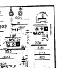
Above voltages were for VR601 wiper, schematic shows typically +1.2V at this point, being 2xVbe to get over TR611 and TR613.
If both channels don't respond to VR then these are looking low. There is something of a trap in this area where the actual circuit
flow might have R618 before VR601, so the wiper is not connected to TR611b, I've seen this before with some yamaha schematics.
The hifiengine SM board layout is not real clear, there is some doubt but probably board layout matches schematic, ie, wiper
connects to TR611base/TR607e. Would be nice to get confirmation.

Below is the area of interest, are you able to post a pic, without board removal, otherwise wait for others to chime in.
upload_2020-6-27_19-6-13.png

Also plz confirm that both L&R don't respond to VR bias adjustment (TP1&TP0)
 
Maybe I should just get on and
- remove right amp board
- test R627 for 4.7ohms
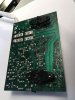
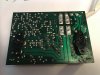
- photograph solder side of board and post it
then await instruction?
 
Right amp board.
R627 is 5.1 ohms
R628 is 5.0 ohms
R633?? reads 0.4 ohms (It's the same type, colour (green) and spec as the other two and is located just above TR613. There are only three of these on the board.)
The continuity tester beeps.
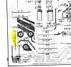
The readings for it are identical on the left board. Marked in yellow on photo.
66399EB2-DF25-4DB0-AC46-84E201B3CEA5.jpeg
 
Back
Top Bottom