Beavs
Active Member
Well, I'm pretty new to this and probably have no business digging into the likes of a CR-2040, but this is what I've found to pass the time and I'm enjoying every second of it.
I picked this CR-2040 up for $200 knowing it was cosmetically great aside from being dirty and there was no sound out of the right channel. It arrived and I started the process of figuring out what's going on. Power up on DBT and in STEREO, no sound out of right channel. Switch to MONO and both channels producing sound. Controls and switches are scratchy as expected so I get into it to Deoxit (D5, D100, and F5 per other threads direction depending on switch/pot type). After cleaning, it is sounding pretty good aside from the Presence potentiometer which is either shot or there is other problems in the tone circuit (heavy scratch and popping when turning Presence pot, way worse than prior to cleaning). But so far I'm pretty stoked based on a $200 gamble on this thing.
Desoldered the Presence pot (VR601) and partially pulled the front interior face plate to pull it out and give it its own bath. Soldered it back in and no change from before, so either VR601 is shot or something else in the Tone Control board (POWER C.BOARD(2) per the SM) or elsewhere.
Next step was to go through the Power Section adjustment and Audio Section adjustment from the SM before starting to slowly and carefully try to diagnose this. SM procedure isn't the clearest on this, clear and simple direction found from Merrylander here:
https://audiokarma.org/forums/index.php?threads/dc-offset-for-yamaha-cr-2040.104808/
And now, the depressing part. Even with the clear direction from Merrylander in the thread above, as well as numerous other threads I've read in the past, I have small insulated (mostly but not enough) alligator clip leads that I use for these measurements. Had made it through the Power, DC, and Bias adjustments, then came back through after 5-10 minutes to check again and adjust as needed and made through Power, DC, Bias on Right Channel and then it happened....The cable of one of the DMM probes slipped from where I had it propped up and then pulled the probe off the table pulling the alligator leads with it and shorted the O pin and the -60 pin on the MAIN C.BOARD-R. (been two days, still feel sick to my stomach on this one)
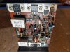
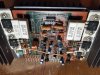
Small smoke plume from the POWER C.BOARD(1) and powered down as quickly as I could. Start inspecting this board closely (seven times now) and all I can visibly see that was toasted and made the plume is the zener diode D909. 10A fuse blew, 3A fuses both still good. Per Merrylander's info from the other linked thread, sounds like the output transistors may have gone as well but no telling just yet.
Before this pin short, I was pretty close to having this up and running with minimal teardown, but just to access the power amp board it's looking like this is going to be a full teardown. If I'm doing that, I'd like to replace any known suspect parts in addition to whatever I have already fried. Hell, if it's all apart, should all electrolytics be replaced? Putting the money into this is well worth it to me.
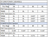
Pulling apart, testing, soldering, unsoldering is no issue for me....the tracing/diagnosing of the problem and then identification of replacement parts however I'm learning and would appreciate all the help I can get. I pulled the datasheet for this zener diode D909 and then go on Mouser and Digikey and Parts Express to try to find a replacement using values from the datasheet and either I'm left with no item results or ones that don't seem to match other values from the datasheet of the original. Transistors pretty much the same results. Resistors much easier to identify. Capacitors, haven't gone down that road yet...
So here I am with at a bare minimum a fried zener diode D909 and need to figure out where to go from here. Nothing is local for a parts source so online ordering for parts is my only option. The shipping cost and delay in receipt of parts is not ideal, so I would hope to minimize the number of shipments (extra parts is not bad). Thanks in advance to any kind souls that are willing to help out!
I picked this CR-2040 up for $200 knowing it was cosmetically great aside from being dirty and there was no sound out of the right channel. It arrived and I started the process of figuring out what's going on. Power up on DBT and in STEREO, no sound out of right channel. Switch to MONO and both channels producing sound. Controls and switches are scratchy as expected so I get into it to Deoxit (D5, D100, and F5 per other threads direction depending on switch/pot type). After cleaning, it is sounding pretty good aside from the Presence potentiometer which is either shot or there is other problems in the tone circuit (heavy scratch and popping when turning Presence pot, way worse than prior to cleaning). But so far I'm pretty stoked based on a $200 gamble on this thing.
Desoldered the Presence pot (VR601) and partially pulled the front interior face plate to pull it out and give it its own bath. Soldered it back in and no change from before, so either VR601 is shot or something else in the Tone Control board (POWER C.BOARD(2) per the SM) or elsewhere.
Next step was to go through the Power Section adjustment and Audio Section adjustment from the SM before starting to slowly and carefully try to diagnose this. SM procedure isn't the clearest on this, clear and simple direction found from Merrylander here:
https://audiokarma.org/forums/index.php?threads/dc-offset-for-yamaha-cr-2040.104808/
And now, the depressing part. Even with the clear direction from Merrylander in the thread above, as well as numerous other threads I've read in the past, I have small insulated (mostly but not enough) alligator clip leads that I use for these measurements. Had made it through the Power, DC, and Bias adjustments, then came back through after 5-10 minutes to check again and adjust as needed and made through Power, DC, Bias on Right Channel and then it happened....The cable of one of the DMM probes slipped from where I had it propped up and then pulled the probe off the table pulling the alligator leads with it and shorted the O pin and the -60 pin on the MAIN C.BOARD-R. (been two days, still feel sick to my stomach on this one)
Small smoke plume from the POWER C.BOARD(1) and powered down as quickly as I could. Start inspecting this board closely (seven times now) and all I can visibly see that was toasted and made the plume is the zener diode D909. 10A fuse blew, 3A fuses both still good. Per Merrylander's info from the other linked thread, sounds like the output transistors may have gone as well but no telling just yet.
Before this pin short, I was pretty close to having this up and running with minimal teardown, but just to access the power amp board it's looking like this is going to be a full teardown. If I'm doing that, I'd like to replace any known suspect parts in addition to whatever I have already fried. Hell, if it's all apart, should all electrolytics be replaced? Putting the money into this is well worth it to me.
Pulling apart, testing, soldering, unsoldering is no issue for me....the tracing/diagnosing of the problem and then identification of replacement parts however I'm learning and would appreciate all the help I can get. I pulled the datasheet for this zener diode D909 and then go on Mouser and Digikey and Parts Express to try to find a replacement using values from the datasheet and either I'm left with no item results or ones that don't seem to match other values from the datasheet of the original. Transistors pretty much the same results. Resistors much easier to identify. Capacitors, haven't gone down that road yet...
So here I am with at a bare minimum a fried zener diode D909 and need to figure out where to go from here. Nothing is local for a parts source so online ordering for parts is my only option. The shipping cost and delay in receipt of parts is not ideal, so I would hope to minimize the number of shipments (extra parts is not bad). Thanks in advance to any kind souls that are willing to help out!