

You are using an out of date browser. It may not display this or other websites correctly.
You should upgrade or use an alternative browser.
You should upgrade or use an alternative browser.
Yamaha M-50 restoration /recap kits on eBay
- Thread starter RoddyRod
- Start date


Yeah,those are the ones I spent alot of time cleaning.LOL, these look pretty clean to me, almost mint …

Sparkplug
Super Member
Good job … please post photos of the solder side as well …Yeah,those are the ones I spent alot of time cleaning.
You're lucky you don’t have any noticeable corrosion and the big caps are in good shape.
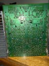



Other than the dirt,I couldn't see any blow components or anything that look like it was about to go. I did talk to the previous owner again about what speakers he was running with this and he did mention he ran them with 4 ohm speakers, Infinity reference 80's. Are those known to be hard to drive speakers?
Sparkplug
Super Member
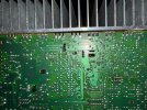
The solder-sides generally look clean but it’s hard to tell because the photos aren’t high res enough and upon enlargement, things blur up a bit. Nevertheless I picked a few cold solder joint looking ones that may need attention, see below.
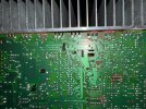
Anytime you see dried up solder joint forming concentric circles, reflow them, they’re time bombs. If I were you, I’d take the time and reflow every single solder joint, including RCA connector board connections.
Anytime you see dried up solder joint forming concentric circles, reflow them, they’re time bombs. If I were you, I’d take the time and reflow every single solder joint, including RCA connector board connections.
Last edited:
Yeah,I did notice that too. the input board had some like that too before I de-soldered it. Before I cleaned it up, pools of flux covered some of the spots that look like they could be cold joints, like the ones on the output transistors you pointed out. Besides seeing some of the bulbs replaced ,I have some suspicions that more work may have been done before ,but sometimes things look a little sloppy from the factory.
Sparkplug
Super Member
You don’t have much to worry, it’s just the general wear and tear that goes with age. Take care of the details before putting it into service.Yeah,I did notice that too. the input board had some like that too before I de-soldered it. Before I cleaned it up, pools of flux covered some of the spots that look like they could be cold joints, like the ones on the output transistors you pointed out. Besides seeing some of the bulbs replaced ,I have some suspicions that more work may have been done before ,but sometimes things look a little sloppy from the factory.
- Check and possibly change the relays if they’re original
- Make sure the trimmer pots are healthy and not fragile, you could change them with Bourns multiturn pots except for the idle current setting ones that are larger than normal
- Check the electrolytic cap board ground wire soldering, sometimes they have cracks
- On the front panel meter board, you might want to reflow all LED solder joints, they often stop working not because they’re bad but because their have cold solder joints
Good luck.

Yeah, i was thinking it could be another hint it was worked on before.Someone was pretty liberal with the transistor heatsink compound.. About 10X more than needed.
Sparkplug
Super Member
Any capacitor in the audio path or hanging from audio path (to ground, etc.), use audio grade replacement capacitors. The big smoothing caps in the power supply board, the current powering your speakers is the ripple current flowing through them, choose the best. For M-50, these are perfect (believe me, I’ve done my homework on this) but you’ll have to do some simple rework:So looking around on the net and I see the audio grade nichicon muse capacitors come up a lot. Anyone have experience with those? H,bout the big 10k uf 63v capacitors , does audio grade matter for those?
The lead spacing for these snap-in negative black Chemi-Con caps (same brand as originals) is 10mm versus 22.5mm for the 5-pin originals. The size is almost the same, 35mm x 60mm versus 40mm x 60mm (OEM) … and these are 15000uF 63V versus 10000uF 63V for the originals. Last week I finally bit the bullet and replaced all 4 in my B-50, you’ll have to drill a few ø2mm holes followed by scraping a bit of solder mask for soldering to accommodate these, a very easy job and the board layout with big fat traces makes it a walk in the park.
What I did (see below), was to first mark the original caps outlines on the board (yellow circles) to see where they sit, otherwise the electrolytic cap board won’t fit back in its place. Then I drilled ø2mm holes along the red lines connecting the two original capacitor mounting holes. The new caps have to sit on that line and inside the yellow circles. You can either drill two ø2mm holes 10mm apart, or use an existing hole and drill another one 10mm away while making sure the new cap sits in its corresponding circle.

Last edited:
Sparkplug
Super Member
They are more than capable of handling a few thousand more uF’s, even 20000uF would not be an issue here but the size won’t fit. I chose these because of nearly identical physical size and that they are the same series as the originals.Interesting. 5000 more microfarads. I wonder if the rest of the power components can handle the extra capacity? Ill look into it.
Having said all this, your originals may be still good, need to carefully take them out and measure them.
Wow. Some of these caps that I am trying to replace are being discontinued. Now it looks like it is going to be more like a treasure hunt. I am trying to stay with the same line of caps but some voltages are not available. I know I could go a little higher but some caps are only available with the same mf values but with double voltage capacities! Looks like I may have to mix and match different nichicon lines to get all the same mf values and reasonably closer voltage values.

The best manuals money can buy are Normans at Analog Alley.. Even better than the original paper manuals..Any place I can find more detailed schematics of the main amplifier board?
Yamaha M-50 service manual, Analog Alley Manuals
www.analogalley.com