• The move to the new server is done. There are some software and database maintenance updates in process. This has us passing the hat around to help out. We appreciate any donations. Seriously, even a dollar helps. The payment page may be found here - https://www.audiokarma.org/support.html

Yamaha M-50 restoration /recap kits on eBay

Looks like the one that is available around the internet, which doesnt have the schematics of the main board. Is this one any different? Has anyone downloaded this one and can verify it has all the schematics available .

Yes I have it. It is a complete manual. Analog Alley is the only place I get my Yamaha manuals if I have to purchase any manuals.
It is a Hi-Q color scan. Better than any original document.
 
Last edited:
Looks like the one that is available around the internet, which doesnt have the schematics of the main board. Is this one any different? Has anyone downloaded this one and can verify it has all the schematics available ?
You'll notice the difference when you try to print or zoom in. Norms are super high quality and equal to an original print. I have at least 4 manuals from him and the difference between the freebies is night and day.
 
They are more than capable of handling a few thousand more uF’s, even 20000uF would not be an issue here but the size won’t fit. I chose these because of nearly identical physical size and that they are the same series as the originals.

Having said all this, your originals may be still good, need to carefully take them out and measure them.
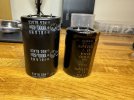
I found some elna 15k uf that are just a tad shorter. With the extra space, it should save me from having to modify the board to make em fit.
 

Attachments

  • IMG_0087.jpeg
    IMG_0087.jpeg
    38.3 KB · Views: 4
Since I have room in height am going to create some spacers to put under the caps and solder some solid copper wires to get to the spacing I need. I don't want to modify the board because it feels flimsy as it is.
 
I wouldn’t do it that way but it’s your amp, good luck … :thumbsup:
Make sure your solder connections are solid and there are no shorts (disaster).
:lurk:
 
Oh, and one more thing, you should measure the original caps first before replacing them, they could be perfectly fine and in spec.
 
While removing the heat sinks, i was suprised to see how loose the screws that mount the output transistors were torqued down. Feels like literally no effort to turn the screws. These had a thick layer of heat sink grease between the insulator and the transistor itself. Comparing to other amps I have disasembled, this is just ridiculous! I didnt try, but im willing to bet if i torqued the screws down a little more, i could have squeezed out some of the excess grease from behind the transistors! Is there any reason I may not know about on why something like this is done??
 
Sounds like someone's been there before. I haven't worked on a 50 but every 80/85 I've had, the screws were very tight and no excess compound to speak of. I suppose someone could have been sloppy at the factory that day but I doubt it.
 
Sounds like someone's been there before. I haven't worked on a 50 but every 80/85 I've had, the screws were very tight and no excess compound to speak of. I suppose someone could have been sloppy at the factory that day but I doubt it.
Oh for sure I know this has been worked on before. I really doubt the factory would let something like this go.
 
there should be a little break away when trying to loosen the screws.
About 12 inch/lbs..:biggrin: Be glad they didn't use epoxy ..:biggrin: Or pull the threads out of the heatsink. Or cross thread a screw in the heatsink..
 
Back
Top Bottom