

You are using an out of date browser. It may not display this or other websites correctly.
You should upgrade or use an alternative browser.
You should upgrade or use an alternative browser.
Yamaha RX-730
- Thread starter Smoky D
- Start date
Register to hide this ad
Hello everybody,
14 years later, following up on this really old thread. Came across the same model with the same problem. Any ideas on how to get started on troubleshooting this problem? The service manual is available now on HiFiEngine.
Will definitely appreciate your help. Thanks.
14 years later, following up on this really old thread. Came across the same model with the same problem. Any ideas on how to get started on troubleshooting this problem? The service manual is available now on HiFiEngine.
Will definitely appreciate your help. Thanks.

First I visually look for cooked resistors in the output stage and in the protect ckt. Then I perform crude in ckt tests of the output trannies with a DMM diode/continuity checker function looking for hard shorts. Then I compare how it acts on a normal power outlet and compare it with how it acts on a dim bulb tester.
No matter the power source. I test DC voltage on the speaker terminals hoping for less tham 50mV if the protect ckt allows. hoping for at least a 1 second snapshot of a health reading.
I also ask myself if I heard the first relay click, the soft start, and then did I hear the 2nd relay click 3 seconds later activating the output stage.
No matter the power source. I test DC voltage on the speaker terminals hoping for less tham 50mV if the protect ckt allows. hoping for at least a 1 second snapshot of a health reading.
I also ask myself if I heard the first relay click, the soft start, and then did I hear the 2nd relay click 3 seconds later activating the output stage.
Last edited:
Visual check did not show any abnormal or burned resistors. The DC voltage on the speaker terminals is slightly above 0 mV. There is one relay click immediately after the power turns on. No second click. Some other threads mention the blown LED bulb for the back-light and its relation to the protection module. Yes, this bulb is toast. I disconnected it and tried to use a fresh LED. It was lit for 3-4 sec the first time it was connected and then dimmed out. Never produced any light again. It still works fine with the external power. I checked it from 3V to 9V and it was ok. Now, the DMM shows less than 5 mV on the wire that's supposed to power the LED, and that's steady 5 mV no matter how long I measure it. There is also no power going to the LED on the volume control and the is absolute silence on the speakers, no crackling, no hum, nothing. But the main LCD display turns on and I can see the info on it when I change the source or press the presets. Of course the display is pretty dark and I have to use an external light shining on the back of it to be able to see anything.First I visually look for cooked resistors in the output stage and in the protect ckt. Then I perform crude in ckt tests of the output trannies with a DMM diode/continuity checker function looking for hard shorts. Then I compare how it acts on a normal power outlet and compare it with how it acts on a dim bulb tester.
No matter the power source. I test DC voltage on the speaker terminals hoping for less tham 50mV if the protect ckt allows. hoping for at least a 1 second snapshot of a health reading.
I also ask myself if I heard the first relay click, the soft start, and then did I hear the 2nd relay click 3 seconds later activating the output stage.
Then I crack a beer for a re-think synopsis attack plan...maybe two...then divide & conquer.
What are the basic steps for testing of the protection module from your experience?
Did the speaker relay kick in???The DC voltage on the speaker terminals is slightly above 0 mV.
Better to measure dc offset between the emitter resistors, measure at either leg as shown, repeat for other channel to the "south"
Attachments
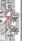
measure voltages at each pin belowSome other threads mention the blown LED bulb for the back-light and its relation to the protection module.
Attachments
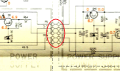
Sorry, I have to confirm. The DMM on DC voltage and one probe at either leg of those resistors, the other one at the chassis?Better to measure dc offset between the emitter resistors, measure at either leg as shown, repeat for other channel to the "south"
Yep.The DMM on DC voltage and one probe at either leg of those resistors, the other one at the chassis?
Instead of chassis you can clip the black probe to any black speaker post/connector, it is also GND.
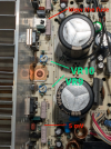
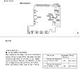
I did the measurement/Idling Current Adjustment, page 6,7 of the Service Manual. As per the manual the VRs are 9 and 8, but in reality they are VR9 and VR10(see the attached pics). I'd guess it is just a typo. Black probe to the black speaker terminal, the red one to the points marked in red on pic RX-730-1 i.e. the Left channel shows 5 mV, and the Right blew the fuse when connected the DMM. I replaced the fuse and the unit is in the same state as before.
Attachments
Last edited:
Yes, typo in sm, both adjustments, schematic and board layout incorrectly show VR8,9. VR9 and 10 are correct.As per the manual the VRs are 9 and 8, but in reality they are VR9 and VR10(see the attached pics). I'd guess it is just a typo.
Important to note that the black probe is grounded only for the DC offset measurement. For the idle adjustment, the black probe is connected to the other side of the resistor (not grounded!!!) as per the sm.Black probe to the black speaker terminal, the red one to the points marked in red on pic RX-730-1
"Impossible" for fuse to below if you were measuring dc offset correctly. Possibilities are you accidently shorted on one of the nearby jumpers or you had your DMM set to resistance/ohms. Since the fuse blew it's very likely you have damaged others parts most probably outputs Q102,4 and/or drivers Q28, Q30. These transistors should be diode tested (below). Do you have a dim bulb tester, you will probably need one, it's a current limiting device useful for troubleshooting shorts(saving fuses...lol) Numerous plans on AKthe Right blew the fuse when connected the DMM.
Nice graphic from markthefixer on diode testing
Attachments
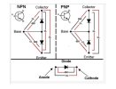
It would be very helpful if you could identify what pins you shorted, best guess is fine, we can then try and work out what else is suspect faulty.
Suggest you build a Dim Bulb Tester, uses an old incandescent bulb, plenty of plans on AK.
Also suggest pull the output transistors and in their place connect whatever diodes you have at hand, eg, 1N4148, 1N400x... between the base and emitters for NPN diode anode to base, for PNP cathode to base. By connecting diodes between base and emitter tabs completes the circuit, the diodes emulate the transistor b-e junction. Then DBT power up, do not attempt to set bias on dbt/with diodes in place. Looking for a dim dbt.
When the time comes to set the bias connect MM across one of the emitter resistors, shown in blue and purple for L&R channels. If access is difficult it's ok to connect to the other resistor immediately next to it.
Suggest you build a Dim Bulb Tester, uses an old incandescent bulb, plenty of plans on AK.
Also suggest pull the output transistors and in their place connect whatever diodes you have at hand, eg, 1N4148, 1N400x... between the base and emitters for NPN diode anode to base, for PNP cathode to base. By connecting diodes between base and emitter tabs completes the circuit, the diodes emulate the transistor b-e junction. Then DBT power up, do not attempt to set bias on dbt/with diodes in place. Looking for a dim dbt.
When the time comes to set the bias connect MM across one of the emitter resistors, shown in blue and purple for L&R channels. If access is difficult it's ok to connect to the other resistor immediately next to it.
Attachments
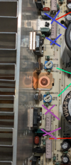
Last edited:
I was measuring the Idling current. The right channel showed 5 mV when the black probe was clipped to the negative speaker terminal in the back and the red probe connected to the 2nd from the top check point marked with a purple cross on the photo above. Then I tried to move the red probe to the top point marked with a blue cross. The short was instantaneous and the fuse went off immediately. I might have touched both legs of the big grey/pink resistors there but according to the schematics they are supposed to be connected anyways. I can't tell if I touched any other pins. It happened very fast.
I ordered the whole set of the transistors to swap. Output and drivers (4 + 4). When I get them, I'll start replacing them with the right channel first and will check if the originals are damaged.
Then, I will connect both probes of the DMM to the opposite sides of the resistors marked wit blue and purple crosses. I noticed that I am repeating myself a lot. But it's only because I don't want to screw up that box again by doing smth wrong. Sorry.
Right now after I replaced the fuse, the unit powers on ok and stays on. No sound, as expected.
I ordered the whole set of the transistors to swap. Output and drivers (4 + 4). When I get them, I'll start replacing them with the right channel first and will check if the originals are damaged.
Then, I will connect both probes of the DMM to the opposite sides of the resistors marked wit blue and purple crosses. I noticed that I am repeating myself a lot. But it's only because I don't want to screw up that box again by doing smth wrong. Sorry.
Right now after I replaced the fuse, the unit powers on ok and stays on. No sound, as expected.
Attachments

Your probably confused by terminology, the method you described would be fine for measuring DC offset and in general voltage measurement. As previously explained, bias is measured across one of the emitter resistors as marked in blue and pruple.I was measuring the Idling current.
Most likely you touched the jumper wire (J127) behind R194 which carries +52Vdc abouts. Dumping this sort of voltage at the emitter resistors probably blew parts in the direction of the -ve rail. Candidates for testing areThe short was instantaneous and the fuse went off immediately
- both emitter resistors(test incircuit 0.22ohms so expect less than 1 ohm),
- output Q104. Q102 is probably ok but if Q104 is faulty then replace as a pair.
- driver Q30 again replace as a pair
- R182(5.6k) and R184(5.6k)
Is the unit drawing abnormal current? A dbt will tell you. Suggest you build one, it's just an incandescent bulb in series with the active power. Without it you run the risk of blowing your new components.Right now after I replaced the fuse, the unit powers on ok and stays on
The emitter resistors R188, 190 show 0.4 ohm, all 4 of them, L and R channels.
The R182, 184 should be 5.6k but only measure at 2.8k. Both the same. The other channel R183, 181 are at correct 5.6k.
The transistors will come in by the end of the week. I will let you know the progress.
The R182, 184 should be 5.6k but only measure at 2.8k. Both the same. The other channel R183, 181 are at correct 5.6k.
The transistors will come in by the end of the week. I will let you know the progress.
Odd, I don't see any alternate parts if you measure in-circuit. Also resistors don't drop in value, the check request was looking for failed open due to excessive current.The R182, 184 should be 5.6k but only measure at 2.8k. Both the same
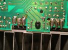

No, it is just the flux residue. Clean the boards well with denatured alcohol and a paint brush and tooth brush so you can see the traces and solder joints more clearly.Do those contacts of the output transistors look like they've been overheated?
Athanasios
Got the output transistors out of the ckt and tested as per the diagram in the prev message. Tested all four. Q101,103,102 satisfied the test. B-2-C showed 0.54-0.53 V on all three of them, using the proper polarity of course. The Q104 is definitely faulty. C-2-E shows voltage, and B(+) to C(-) or E(-) shows 2V as well. My understating is that I should replace the pair Q104 and Q102 and I will. Q28 and Q30 are bad too. Will replace.
Update: replaced all four transistors. No short, no light on the DBT. And no sound. Back to where I started.
Update: replaced all four transistors. No short, no light on the DBT. And no sound. Back to where I started.
Attachments
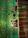
Last edited:
There is something that I am not clear about this unit. It was mentioned in a few other threads before and I did not find an answer.
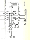
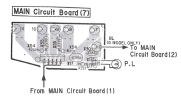
If you look at the schematics attached to this message, there’s the transformer that provides power to other components of the amp through points 7,8,9,10 and 11. A light bulb is powered from points 9 and 10, right? This bulb is currently burned and not working. When I tried to measure the voltage at the bulb's connector to find a replacement, I got zero volts, nothing. Can it be the case that some of the resistors on this board (Main Circuit Board 7) failed and disrupted the power flow from the transformer to the other parts? Or is it just a power light of the unit being there for aesthetic purposes only and doesn’t change anything for the functionality?
If you look at the schematics attached to this message, there’s the transformer that provides power to other components of the amp through points 7,8,9,10 and 11. A light bulb is powered from points 9 and 10, right? This bulb is currently burned and not working. When I tried to measure the voltage at the bulb's connector to find a replacement, I got zero volts, nothing. Can it be the case that some of the resistors on this board (Main Circuit Board 7) failed and disrupted the power flow from the transformer to the other parts? Or is it just a power light of the unit being there for aesthetic purposes only and doesn’t change anything for the functionality?
Attachments
It will be an AC voltageWhen I tried to measure the voltage at the bulb's connector to find a replacement, I got zero volts, nothing