

You are using an out of date browser. It may not display this or other websites correctly.
You should upgrade or use an alternative browser.
You should upgrade or use an alternative browser.
Yamaha RX-730
- Thread starter Smoky D
- Start date
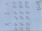

Check for loose or half seated ribbon cables as you go along...Like the ladies say, sometimes it's the little things.
Edit: Thin white stripes joining boards together. I've fixed a few RX's & RX-V's from this era doing this. Sometimes they come loose from sag weight over time.
Edit: Thin white stripes joining boards together. I've fixed a few RX's & RX-V's from this era doing this. Sometimes they come loose from sag weight over time.
Last edited:
Edit ^

Easier to attach the photo than to type

audiotemp
Super Member
If you measure this, add pin 6 to the list. So, pins 6, 9, 10, and 11. This would be across 100k resistors R48, R49, R50, and R51.I would like to know resistance (with power off) between chassis gnd and each of ic 7 and ic 8 pins 9, 10, and 11.
GND to IC7, IC8If you measure this, add pin 6 to the list. So, pins 6, 9, 10, and 11. This would be across 100k resistors R48, R49, R50, and R51.
p6 = 100k 100k;
p9 = 3.5k 3.45k;
p10 = 5.5k 5.6k;
p11 = 15.9k 16k;
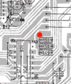
Those measurements are taken from GND at the speaker terminal and also from the point on the pic below. They appear to be identical.
Attachments
Last edited:
audiotemp
Super Member
Pin 6 is not connected to an ic 6 output like the others are. Also interesting how different the pin 11 number is from nominally identical pins 9 and 10. I think those numbers point somewhat towards a problem with ic 6 but not definitely so.GND to IC7, IC8
p6 = 100k 100k;
p9 = 3.5k 3.45k;
p10 = 5.5k 5.6k;
p11 = 15.9k 16k;
Also puzzling are the IC6 input voltages (from IC4) they are the same for DAT and VCR. The LED for selected input is correctly illuminated. Then there's the issue of LD output regardless of selected source
edit
IC4 P60, 61, 62 High is Vdd-1.8V so abouts 3Vdc, IC6 has a high at 2.2V and a low at 0.4V means DAT and VCR are mostly between H & L into IC6. Could faulty IC6 be dragging down these voltages???
edit
IC4 P60, 61, 62 High is Vdd-1.8V so abouts 3Vdc, IC6 has a high at 2.2V and a low at 0.4V means DAT and VCR are mostly between H & L into IC6. Could faulty IC6 be dragging down these voltages???
Last edited:
audiotemp
Super Member
Yes, all the voltages are low. Low (or dragged down) from ic 4 and same from ic 6.
Guaranteed input logic levels for ic 7,8 are roughly > 6v (for "high" ) and < 3v (for "low" ). In between you don't know what you will get and it is not good for the ic besides.
Similarly, inputs to ic 4 should ideally be > 2.2v to ensure its full "high" output level of 8+ volts (or less than 0.4v for low, as noted by mbz above).
Removing ic 6 would clear up cause vs. effect but obviously difficult to remove it and maybe not cheap to replace it.
Guaranteed input logic levels for ic 7,8 are roughly > 6v (for "high" ) and < 3v (for "low" ). In between you don't know what you will get and it is not good for the ic besides.
Similarly, inputs to ic 4 should ideally be > 2.2v to ensure its full "high" output level of 8+ volts (or less than 0.4v for low, as noted by mbz above).
Removing ic 6 would clear up cause vs. effect but obviously difficult to remove it and maybe not cheap to replace it.
Last edited:
What would happen if it is removed? No voltages to IC7,8 and as a result no signals sent to the pre-amp, via Volume ctrl, and as a result no sound on the speakers? I'm not familiar with those ICs, is it silly to ask if there is a "default" state/connection for IC7,8?
That's why I was asking in #210
LB1294 is about $15 new on eB.
That's why I was asking in #210
LB1294 is about $15 new on eB.
The point to removing IC6 would be to see if the voltages on those solder blobs/pins normalized so could conclude IC4 is working ok and confirm something (IC6 internals?) is dragging down the voltages.What would happen if it is removed? No voltages to IC7,8 and as a result no signals sent to the pre-amp,
Don't know the amp, suspect that there is always one source selected, problem is the IC4/IC6 interface is not working as expected with some voltages not meeting the high or low threshold.ask if there is a "default" state/connection for IC7,8?
The amp is somewhat useable with CD Direct and LD "working", if you want better/full functionality then need to spend the time... I wouldn't rush buying parts on the bay