

You are using an out of date browser. It may not display this or other websites correctly.
You should upgrade or use an alternative browser.
You should upgrade or use an alternative browser.
Yamaha RX-730
- Thread starter Smoky D
- Start date

audiotemp
Super Member
If you measured those voltages directly at the volume control, then the problem is upstream of that. So, either at the upstream part of the CD direct switch or at the mux ic. Follow the signal voltage upstream through the switch.Vol ctrl in CD Direct mode: min=0.001 V, max up to 0.250 V and it varies.
in CD mode: min=0.001 V, max=0.009 V and it stays on that.

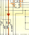
Input selector is set to CD. With black meter probe connected to the black speaker terminal GND and the red one to IC7 pin14 there is constantly changing voltage around 0.250 V to 0.030 V. Connecting the red probe to pin3 brings the measurement of 0.030 V permanent. If that is the path from the CD rca connection to the Volume ctrl -- the IC7 isn't doing its job. Actually both, IC7 and IC8 for the R-channel as well.
How do I test them more consistently?
How do I test them more consistently?

I don't want to speak ahead of an unproven issue but...if the op amp proves bad I like to install socket adaptors for future fun. With adaptors I can quickly swap various op amps until I find the best one, or the one that doesn't blow up. 
Was Yamaha nice enough to install adaptors beforehand?
Carry on gents


Was Yamaha nice enough to install adaptors beforehand?
Carry on gents
A CD player is on CD rca input using a regular music cd.
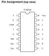
No, the DC voltages on pins 9,10,11 are messed up. Should be p9: 0, p10: 0, p11: 8.2V.
IC7. p16 : 9.4V, p6 : 85mV, p7 : -9.4V, p8 : 0.4mV, p9 : 1.35V, pin10 : 1.33V, pin11 : 1.1V.
IC8. p16 : 9.4V, p6 : 85mV, p7 : -9.4V, p8 : 0.4mV, p9 : 0V, p10 : 0.6mV, p11 : 1.15V.
No, the DC voltages on pins 9,10,11 are messed up. Should be p9: 0, p10: 0, p11: 8.2V.
IC7. p16 : 9.4V, p6 : 85mV, p7 : -9.4V, p8 : 0.4mV, p9 : 1.35V, pin10 : 1.33V, pin11 : 1.1V.
IC8. p16 : 9.4V, p6 : 85mV, p7 : -9.4V, p8 : 0.4mV, p9 : 0V, p10 : 0.6mV, p11 : 1.15V.

Yes this needs to be clarified, if it's music then we can see the fluctuation in the voltages at pin 14. can you use a tone generator app from your phone to connect to the inputs?Do you have stable DC voltages (relative to gnd) on ic 7,8 power and control pins (6 through 11, and 16) that agree with the voltages in the schematic?
What do you have connected to the CD rca input?
It would keep the voltages at an even level at PIN14 of IC 7 and 8.
Measure the voltages on IC 6 , the 8.2 volts for pin 11 should come from IC 6 pin 13.A CD player is on CD rca input.
No, the DC voltages on pins 9,10,11 are messed up. Should be p9: 0, p10: 0, p11: 8.2V.
IC7. p16 : 9.4V, p6 : 85mV, p7 : -9.4V, p8 : 0.4mV, p9 : 1.35V, pin10 : 1.33V, pin11 : 1.1V.
IC8. p16 : 9.4V, p6 : 85mV, p7 : -9.4V, p8 : 0.4mV, p9 : 0V, p10 : 0.6mV, p11 : 1.15V.
Athanasios
Yes, I can. The fluctuation is fine, I am not happy with the voltage being the same on p3.Yes this needs to be clarified, if it's music then we can see the fluctuation in the voltages at pin 14. can you use a tone generator app from your phone to connect to the inputs?
p13: 1.15V should be 8.2VMeasure the voltages on IC 6 , the 8.2 volts for pin 11 should come from IC 6 pin 13.
p4: 1.85V should be 5.3V
Last edited:
Hmm, make me wonder if IC 6 is also bad.1.15V
What are the other voltages, need to track down their source .
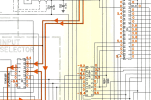
Last edited:
Yeah , some are also off and come from IC4 . Lots of voltages on that chip.IC6.
p2: 2.95, p4: 1.85, p8: 9.4
p9: -9.4, p13: 1.15, p15: 0.68, p16: -0.5
Getting out of my league here. Hopefully though this will lead the others on the right path.
Will continue to follow.
Athanasios
Hmm, make me wonder if IC 6 is also bad.
Yeah, maybe IC6 or maybe bs in bs out. Pin 4 looks like the issue, datasheet shows a high input as +2.2V.IC6.
p2: 2.95, p4: 1.85, p8: 9.4
Maybe an internal failure is dragging down the voltage? mcu fault? If there is a jumper along the path to pin 4 that could be lifted... to rule out mcu
edit no jumper, track directly from mcu
The guiding(?) voltages on IC6 are a bit misleading, pins 1&16 ...6&11 are the same equivalent circuit so how is it possible to get different results for 0V input...
Keep in mind that IC7 is part of input selection, the pin voltages will depend on selected input, the mcu then "loads" the pin voltages to get wanted input. Try selecting PHONO input and see if the pin 11 voltage normalizes
Last edited:
audiotemp
Super Member
The outputs of ic 6 only "pull up". For 0v input, the voltage at the output is determined by the voltage to which an external resistor pulls them down.The guiding(?) voltages on IC6 are a bit misleading, pins 1&16 ...6&11 are the same equivalent circuit so how is it possible to get different results for 0V input...
At the moment the only suggestion I have is to verify that the supply to ic 4, pin 64 is correct.