• The move to the new server is done. There are some software and database maintenance updates in process. This has us passing the hat around to help out. We appreciate any donations. Seriously, even a dollar helps. The payment page may be found here - https://www.audiokarma.org/support.html

Yamaha RX-730

Blue - Red:
+ to - : 0.3 ohm
- to + : 0.5-0.3 ohm

Green - Red:
+ to - : 0.3 ohm
- to + : 0.3 ohm
Looks like a short somewhere to me.
I guess next step would be to remove the caps and check the ohms on the same points again to see if short was the caps or up stream.

Right @mbz ?

Nashou
 
Last edited:
Incircuit measurements can be tricky, reversing the probes was about eliminating flow through rectifier and secondary windings. Measurement points to either outputs Q102, Q104 both c-e short or a solder bridge

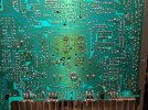
Can you get a hi res pix of the main amp board, solder side (yamaha don't normally have removeable base plates).

Alternatively pull Q102 and Q104 and connect a 470/500ohm resistor between base and emitter solder tabs, alternatively you can connect diodes as mentioned previously
 
Just a recap(?)
Appears to be hard shorts in right power amp stage between +ve rail and GND, also a short between -ve rail and GND. Output c-e short "alone" will not give this result

With black meter probe connected to GND point (red above) measure resistance (amp powered off) at
Q102c to GND
Q102e to GND
Q104c to GND
Q104e to GND

What transistors are Q102 and Q104 (MJ...? or...) Do they require mica insulators?

Did not see and solder bridges, need to keep transistor legs well clear of heat sink
 
All four transistors show similar results. All four have continuity between the c leg(s) and the heat sink. The two new ones (NJW0281G and NJW0302G) sit on thermal paste that is not electrically conductive.
Resistance check:
Q102c to GND : 0.5 ohm
Q102e to GND : 0.3 M
Q104c to GND : 0.5 ohm
Q104e to GND : 0.4 M
 
  • Like
Reactions: mbz
That done, there's some good news. DBT glows only when powered up, no bright light. There is a definite second relay click that was not there before. No smoke from the IC6 and the source input changes OK. Now, not all's so peachy, there is no sound when connected to either of the speaker terminals.
 
That done, there's some good news. DBT glows only when powered up, no bright light. There is a definite second relay click that was not there before. No smoke from the IC6 and the source input changes OK. Now, not all's so peachy, there is no sound when connected to either of the speaker terminals.
How about through headphones?

Nashou
 
So a preamp issue, maybe switches...

Have you tried with Tone Bypass ON?

Assume you are using AUX/CDP to rule out tuner or phono issues

Both channels affected so maybe power supply to preamp.

Also IC7 that you replaced performs input selection, what part did you end up using, suitable pinout?
 
Assume you don't have a scope, you could try using your MM on 200mV AC scale to test/detect audio, black MM probe to black speaker connector.

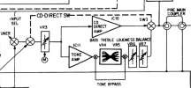
The service manual shows the left channel audio path highlighted.

Play audio, set volume about half way, no need for spkrs/headphone.

Test at the middle pin/wiper of the volume pot, if you detect voltage then increase/decrease vol to see mV increase or decrease. Stop audio, confirm mV drops. No mV would point to input selector IC7 etc...

The preamp is opamp based IC10A/IC11A, possibly opamp failed or no power to opamp.
Carefully measure Vdc at pin 5, repeat for pin 9, expect about +/-9Vdc. The opamp power comes from diode bridge D15, assume all lifted parts/jumpers have been reinstalled.

 
Have you tried with Tone Bypass ON?

Assume you are using AUX/CDP to rule out tuner or phono issues

Both channels affected so maybe power supply to preamp.

Also IC7 that you replaced performs input selection, what part did you end up using, suitable pinout?
The new IC7 is CD4051BE. I replaced both IC7 and IC8. Pinout on those match the originals.
Tone Bypass on/off makes no difference, no sound on both settings.
But with CD Direct the sound is audible and the volume can be changed.
 
  • Like
Reactions: mbz
But with CD Direct the sound is audible and the volume can be changed.
Points to failed tone amp opamp, see block diagram below
Check pins for audio in then audio out.
 

Attachments

  • CD_DIRECT.png
    CD_DIRECT.png
    127.8 KB · Views: 7
The Volume control check shows no voltage on the pot mid pin and GND.
The IC7 received dc on pins16 = +9V and pin7= -9V

Looking into Tone ctrl as per #176
 
The Volume control check shows no voltage on the pot mid pin and GND.
Would expect AC signal (mV) on the middle wiper pin when audio is playing and volume is set high, try at full volume, no spkrs. The vol pot is shared/common for CD Direct and other sources
 
Vol ctrl in CD Direct mode: min=0.001 V, max up to 0.250 V and it varies.
in CD mode: min=0.001 V, max=0.009 V and it stays on that.
 
Vol ctrl in CD Direct mode: min=0.001 V, max up to 0.250 V and it varies.
in CD mode: min=0.001 V, max=0.009 V and it stays on that.
Id the op amps are the same for CD direct op amp and the Tone op amp maybe switch them and see if the
sound switches.
 
Back
Top Bottom