

You are using an out of date browser. It may not display this or other websites correctly.
You should upgrade or use an alternative browser.
You should upgrade or use an alternative browser.
Yamaha RX-730
- Thread starter Smoky D
- Start date
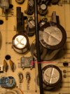
Recheck replaced R230, R231, signs of stress. Try measure in-circuit.same 2mV on the IC7 pin16
Suspect Q36 has died, measure dc voltage one side of R217. Repeat for other side R217.
Alternatively measure at zener and rectifier output, ie, measure 1 red point and one blue.
Attachments
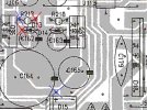
R230, 231 seem to be fine, both ~1ohm.Recheck replaced R230, R231, signs of stress. Try measure in-circuit.
Suspect Q36 has died, measure dc voltage one side of R217. Repeat for other side R217.
Alternatively measure at zener and rectifier output, ie, measure 1 red point and one blue.
R217 both sides = 20mV then drops to 8 mV
Q36e = 8mV. In-circuit testing of this NPN Q36 (without power) with the MM doesn't comply with the usual OL between EC, B black to C red, B black to E red.
still figuring out how to get to the zener D13 and the rectifier D15 safely.
One side of R217 should be rectifier (D15 bridge) output, nominal +15.6Vdc. Can't blame D13.R217 both sides = 20mV then drops to 8 mV
Maybe you have a burnt track? C177 failed (unlikely) D15 failed (unlikely, surge currents are normall xxAmps)
Previously we lifted 2 jumpers to the power amp, anything else still lifted?
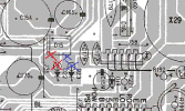
11.8V bothTry measureing Vac (black probe to chassis) at one red point, repeat for one blue point
Nothing else lifted.
Last edited:

audiotemp
Super Member
You mean C164, not C177 ?Maybe you have a burnt track? C177 failed (unlikely) D15 failed (unlikely, surge currents are normall xxAmps)
If there was a sustained downstream short, D15 from both inputs to "+" could open. It's a 1A part while Q36 is likely 2SD1913 at 3A.
yeah C164.You mean C164, not C177 ?
With amp powered off try diode testing D15. Red probe on either ac symbol, black probe on the + symbol. Repeat for the other ac symbol and +, expect 0.55-0.7VIf there was a sustained downstream short, D15 from both inputs to "+" could open. It's a 1A part while Q36 is likely 2SD1913 at 3A.
For the -ve rail need red probe on - symbol, black probe on ac symbol.~ to - : 2.26V
+ve rail looks fine
With only a few mV on R217 I'd be swayed by C164 but that's a sucker bet.
Has C164 been replaced?
suggest diode test D13,
red probe cathode, blk anode gives OL
red probe anode, blk cathode gives 0.55V
C164 looks like factory solder.Has C164 been replaced?
suggest diode test D13,
red probe cathode, blk anode gives OL
red probe anode, blk cathode gives 0.55V
red probe cathode, blk anode gives OL ----- actual 1.2V
red probe anode, blk cathode gives 0.55V ---- actual 0.74V
Incircuit test of D13 can be a bit tricky since you are testing across C162, would have expected the voltage to climb up as the MM charges up C162 eventually OL. Can't explain 1.2V, maybe it collapses to near zero at higher voltage?red probe cathode, blk anode gives OL ----- actual 1.2V
Plz remove or lift one leg and retest
red probe cathode, blk anode gives OL ----- actual 1.2V
Have to replace C162(100/16V), I'm a little sceptical however it matches the measurements...OL with one leg lifted.
I'm not totally convinced about D15, ok it passed diode test but...
If you have some spare time, lift marked leg of R217 then measure Vdc also measure Vac at the lifted leg, trying to test D15, ok there will be no current flow...
Attachments
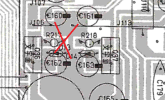
Suggests problem is with C164 or D15. Post #136 should confirm this.R217 both sides = 20mV then drops to 8 mV
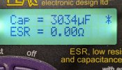
According to the SM, C164 should be 3300 uF 25V. I tested it in ckt. It measures at 3034 uF which is 8% less. Still needs to be swapped? Or should I remove and recheck?
As for D15, AC is measured by one probe on the chassis, one on either of the ~ pins on D15. And DC is measured between + and - pins on it?
As for D15, AC is measured by one probe on the chassis, one on either of the ~ pins on D15. And DC is measured between + and - pins on it?
Attachments
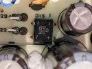
Measure DC with black probe on chassis/GND then red probe on + pin.DC is measured between + and - pins on it?
Then repeat but red probe on - pin
C162 should be replaced because of inconsistent results when testing zener D13Have to replace C162(100/16V),
I would not rush and replace look at D15 againC164 should be 3300 uF 25V. I tested it in ckt. It measures at 3034 uF which is 8% less. Still needs to be swapped?

This looks bad, there should be some output there, Right @mbz ?C162 (100uF/16V) replaced. BTW, the original out of ckt measures at 85 uF.
D15 voltage:
AC 11.72 V this is consistent with #128
DC + or - both very close to 0 V.