

You are using an out of date browser. It may not display this or other websites correctly.
You should upgrade or use an alternative browser.
You should upgrade or use an alternative browser.
Yamaha RX-730
- Thread starter Smoky D
- Start date

Ya know what pisses me off are diodes. I'd replace output transistors and emitter resistors in blown channels and still get haunted by diodes sometimes. Bad diodes create uncontrolled current, especially the zeners.

audiotemp
Super Member
OK, I read through the whole thread and see that the bulb supply must have been shorted. The fuse resistors there were checked/replaced. But I don't see that the DC supply that derives from the same secondary winding as powers the bulb with AC was verified to be working afterwards. It's part of a balanced +/- supply that powers the input circuitry, including those 4051 mux ICs. That supply could still be bad or that chip could just have been damaged at the start but didn't smoke until later. In either case certainly potential for other damage.
Last edited:
I remember it was mentioned in one of the threads that the bulb requires 14V. I used a 12V LED not in series with a resistor and actually it did not die as such. It dimmed out, yes - but later on in a few days I connected it to an external power and it brightened up. After the first try of the LED I never connected anything to the unit again.
audiotemp
Super Member
Probably the (partially) burned fuse resistor limited the current to the LED. But the burned 4051 suggests that the downstream DC supply was affected.I remember it was mentioned in one of the threads that the bulb requires 14V. I used a 12V LED not in series with a resistor and actually it did not die as such. It dimmed out, yes - but later on in a few days I connected it to an external power and it brightened up. After the first try of the LED I never connected anything to the unit again.
What's the plan on this one, parts are available, as a start you could remove the faulty IC then DBT power up (with those 2 power amp jumpers lifted), this may identify further problems.
The failed R230, R231 and the slight glow on DBT when jumpers lifted indicated a problem, maybe just a dying IC or not...
The failed R230, R231 and the slight glow on DBT when jumpers lifted indicated a problem, maybe just a dying IC or not...
If you don't mind going on in diagnosing this unit remotely - I'd be glad to carry on. On my own, I simply don't have enough knowledge, I am way out of that league.
I'll remove the faulty 4051 and try to power on with DBT.
I'll remove the faulty 4051 and try to power on with DBT.
Should I also test the pins 7-11 on the power board? I thought that the initial check of the unit has to use the relay to supply 120V to the main transformer, providing no problems are found. Otherwise those pins have no power by design. And we have not found out the reason why it doesn't pass the initial check.The fuse resistors there were checked/replaced. But I don't see that the DC supply that derives from the same secondary winding as powers the bulb with AC was verified to be working afterwards.
audiotemp
Super Member
A 4051 very much does not like having an input voltage outside the range of its supply voltages and if this happened, it would definitely smoke the chip and quite possibly persist as a short afterwards. If you are up to continue then, yes, remove it as @mbz suggests. Don't replace it until all the PS issues are resolved. (When you do re-install, observe static electricity precautions as it is a cmos chip.)
I think the diagram (post #42) showing AC inputs from the xmfr secondaries on 7-11 is wrong. I think there should be around 25 vrms AC from 8 to 10 and around 80 vrms AC from 7 to 11. And 9 should be a center tap for each.
I think the diagram (post #42) showing AC inputs from the xmfr secondaries on 7-11 is wrong. I think there should be around 25 vrms AC from 8 to 10 and around 80 vrms AC from 7 to 11. And 9 should be a center tap for each.
Removed IC7 4051, powered up with dbt. The unit clicks fast 8-10 times then goes silent. DBT goes from glow to low glow, almost none then stays that way. There is 114 Vac on the main transformer input pins. The output pins 9 and 10 measure at 12 Vac. Which are the other ones you wanted to see?
Last edited:
Maybe measure (Vac) the lot,Which are the other ones you wanted to see?
between 7 & 11 (unregulated supply)
between 8 & 10 (+/-9V supply)
Already done between 9 & 10 (lamps)
between 7 & 11 (unregulated supply) : 71 Vac
between 8 & 10 (+/-9V supply) : 23.8 Vac
between 9 & 10 (lamps) : 12 Vac
Just a remark, I connected the speakers and a CD player through the RCA source currently selected. There was no music coming out of the speakers, but there was some noise and crackling sound from the left speaker only. Both of which are expected as there's no power provided to the R-channel and the IC7 removed.
between 8 & 10 (+/-9V supply) : 23.8 Vac
between 9 & 10 (lamps) : 12 Vac
Just a remark, I connected the speakers and a CD player through the RCA source currently selected. There was no music coming out of the speakers, but there was some noise and crackling sound from the left speaker only. Both of which are expected as there's no power provided to the R-channel and the IC7 removed.

You're gutsy !!! There could be DC on those outputs. Hope they were throw away speakers.between 7 & 11 (unregulated supply) : 71 Vac
between 8 & 10 (+/-9V supply) : 23.8 Vac
between 9 & 10 (lamps) : 12 Vac
Just a remark, I connected the speakers and a CD player through the RCA source currently selected. There was no music coming out of the speakers, but there was some noise and crackling sound from the left speaker only. Both of which are expected as there's no power provided to the R-channel and the IC7 removed.
nashou
Voltages are in the ballpark, were these on DBT, expect yesbetween 7 & 11 (unregulated supply) : 71 Vac
between 8 & 10 (+/-9V supply) : 23.8 Vac
between 9 & 10 (lamps) : 12 Vac
Please measure Vdc at jumper J108(below) = Q36e, nominal 9.4Vdc
Attachments
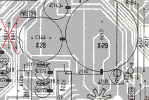
Yep, I believe thats what he means.Yes, the above voltages were taken with the unit on dbt.
Measure Vdc between the J108 (that leads to Q36e) and the chassis (GND), right?
Athanasios
Vdc between the J108 (that leads to Q36e) and the chassis (GND) is only 2 mVdc
Try that, 2mV is not ok, maybe I got the wrong jumper???I can also check it on pin16 on the IC7 socket and GND, correct?