• The move to the new server is done. There are some software and database maintenance updates in process. This has us passing the hat around to help out. We appreciate any donations. Seriously, even a dollar helps. The payment page may be found here - https://www.audiokarma.org/support.html

Yamaha RX-730

This cap is no good.
Even though that tester says it can test parts in circuit , Its best to at least lift one leg and test again just to be sure. As a matter of sanity, I would test all those small Lytics with one leg lifted to be sure.


Athanasios
 
R219,220 - one leg disconnected,
C182 - replaced,
R230,231 - replaced.
Plugged in with DBT and it goes in that cycle again: DBT is off, RY2 clicks once, DBT light goes on to full output brightness, DBT goes off and that starts a new loop.
I have a video clip of that but MP4 files are not allowed to attach.
 
R219,220 - one leg disconnected,
So power goes to power amp "only".
Next step is to identify faulty channel, measure dc offset voltage for each channel, can do at emitter resistors or at R199(L) and R200(R), measure either side to GND.
 
Yeah, you gotta do it while on dbt. The dbt will upset the power amp rails/balance but I'm looking for near rails voltage at mentioned test points. Hopefully both channels wont be the same offset.
 
Thinking 2 possibilities.
Shorted probe in right power amp caused further damage Q24 Q26?
Please measure Vdc one side of R178, repeat for other side, expect about +1.2V and maybe +1V

Other option is fault is downstream 9V regulated supply or the 15V supply, need some thinking time...
 
Vdc on R178 is not stable. It constantly changes. I noticed it going from 1.6 to 2.5 on one side and 0.4 to 1.7 on the other. To test the Q24 and Q26 I need to pull them from the board. Should I do that?
On the attached photo there are connections going from the wall (1) to the small transformer (2), to the relay (3), to the big transformer (4) and through the board (5) to the cable that supplies power to the main board. Judging by that path and the fact that I was not able to confirm any V on pins 7,8,9, do you think that the relay does not let any power to the big transformer? By some logic, I am sure, that exists but we are not aware of the details? Is that what we are trying to figure out?
 

Attachments

  • RX-730-15.jpg
    RX-730-15.jpg
    126.4 KB · Views: 8
The unit will have a standby state, power switched on at wall, power to the small tranformer which then supplies power to the control unit and some other basic functions like infra red receiver... Thinking this supply is basically ok (despite that failed cap???) since it allows progression to the next state.

When you attempt power on (from STBY state) the control unit receives a power on request, it checks if power up is allowed, if so it will order(Q41base) the main power relay to close, so power is supplied to the main transformer. It is at that time a fault is detected, abnormal current flow blowing F1 on main tranformer feed. I don't understand why the amp/dbt cycles, would have thought power up would be aborted for such a fault.

When going from STBY to power on there should be AC on those pins 7,8,9 for maybe 1 second

There is abnormal current draw somewhere downstream of F1
The possible candidates are,
+/-B supply to power amp
+/-13V supply, lifting R219, R220 and dbt still bright eliminates this as a source
+40V supply(via D19) to protect circuit
+15V supply (via D22, D23)
+/-9V requlated supply(viaQ36, Q37)
15V supply via Q39

The likely candidate is the +/-B supply since it's unregulated, faults in the other streams likely to blow a transistor.
Also that is were the probe slip occurred...

Vdc on R178 is not stable. It constantly changes. I noticed it going from 1.6 to 2.5 on one side and 0.4 to 1.7 on the other.
Instability possibly caused by the DBT cycling. Those voltages are not excessive, the low voltage side should be about +1.2V. Q24 looks ok

To test the Q24 and Q26 I need to pull them from the board. Should I do that?
Hold on that, R178 voltages look kinda ok.

Need to isolate the power amp to remove/confirm as candidate.
 
Just wanted to recommend turning VR9 & VR10 all the way down while isolating this. The idle current adjustment.
And good luck as well.

Saying this cuz I've had bad experiences with trim pots labeled "222" on a couple pieces like this one. They had an open spot along the turn track around the factory set point on one channel. That open spot can blow up outputs.
 
Last edited:
  • Like
Reactions: mbz
Just wanted to recommend turning VR9 & VR10 all the way down while isolating this. The idle current adjustment.
Did you mean VR8 and VR9 pre-set potentiometers B 2.2k?
I did not test them on Vdc. But both show similar resistance of 2.2k to 0.5 ohms. I left them both at max res to bring down the voltage on the pins.
Same behavior on power on, DBT blinks constantly.
 
Last edited:
Did you mean VR8 and VR9 pre-set potentiometers B 2.2k?
Yep they are the VR's for bias, need to set to minimum resistance between wiper and other not connected leg. I don't think you will get sensible results if you use the bias test points.
 
Cool, just wanted to make sure they were turned down. Counter clockwise should be minimum, to eliminate simple things. Carry on gents.
:beerchug:
 
Last edited:
Yeah, I've got nothing new, I'd go baby steps and pull parts to isolate various parts.

The first step is trivial, pull the 5Pin connector on the main(7) board then dbt power up. This isolates "everything" on the main transformer. Expect one relay click, dbt to flash then dim. Will look at next step
 
Last edited:
Next step, reconnect 5P connector on MAIN(7) then lift one leg of R230 and R231 also on MAIN(7), these resistor were previously replaced.

DBT power up, note if bulb remain bright also any second relay click
 
pull the 5Pin connector on the main(7) board then dbt power up. Expect one relay click, dbt to flash then dim.
One click. DBT off, no flashing.
reconnect 5P connector on MAIN(7) then lift one leg of R230 and R231 also on MAIN(7)
DBT power up, note if bulb remain bright also any second relay click
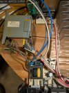
One click, DBT bright then off. Cycles on that until powered off.
 
Reconnect R230 and R231, also R219 and R220 if still lifted.

Possible paths are via D18 and D19 rectifiers.

Trying to isolate the right power amp.
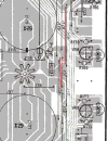
Lift Jumpers J51 and J121, repeat dbt power up
 

Attachments

  • Jumpers.png
    Jumpers.png
    520.2 KB · Views: 4
Back
Top Bottom