

You are using an out of date browser. It may not display this or other websites correctly.
You should upgrade or use an alternative browser.
You should upgrade or use an alternative browser.
Yamaha RX-730
- Thread starter Smoky D
- Start date

What about voltage AC on either side of R230?Unplugged: R230 - 308 ohm, continuity - OL; R232 - 5.1 ohm, continuity - beep; R 231 - 14 Mohm, continuity - OL;
Power ON: pin 9 (black) to pin 10 Vac = 0; each side of the R232 Vac = 2 mV ac;
Nashou
Does not look goodPower ON: pin 9 (black) to pin 10 Vac = 0;
My SM has R230 as 1ohm 0.25W flameproof. Can you check for any markings/post a pix however measurement suggests toasted.R230 - 308 ohm
SM has 4.7ohms 0.25W so okR232 - 5.1 ohm
Failed open, replace, post pix, sm has 1ohm 0.25W flameproofR 231 - 14 Mohm,
These R230 and R231 look not pretty. I'll try to locate the replacements. 1 ohm 0.25 W flameproof. Is flameproof the same as Metal Film Resistor or Carbon-Film Resistors?
Something like these? https://www.mouser.com/ProductDetail/KOA-Speer/MF1-4CL1R00F?qs=61XiPJbgCR0dwBrE/u7jPQ==
Something like these? https://www.mouser.com/ProductDetail/KOA-Speer/MF1-4CL1R00F?qs=61XiPJbgCR0dwBrE/u7jPQ==
Attachments
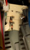
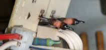
Last edited:
Is that as in one probe on pin9 then measure Vac on one side of R230 and again for the other side?What about voltage AC on either side of R230?

Yes and No.. Key is Flame proof coating like these. As long as the datasheets clearly specify flame resist, proof or retardant.Is flameproof the same as Metal Film Resistor or Carbon-Film Resistors?
Last edited:

Yes.Is that as in one probe on pin9 then measure Vac on one side of R230 and again for the other side?
Am I right assuming that the bulb requires 15 Vac?
First need to sort out why you have no Vac between pins 9 & 10Power ON: pin 9 (black) to pin 10 Vac = 0;
edit looks like pin 9 & 10 are halfwave rectified giving 15.9Vdc so 15Vac wont do it.
Okay. The replacement resistors are on the way.First need to sort out why you have no Vac between pins 9 & 10
Have you done this yet?What about voltage AC on either side of R230?
Nashou
I didn't see a result yet.
You can still check the one side, just to make sure the transformer is okNot yet. R230 is bad and it's up for a swap in a few days, so I will do that check right after.
Trashed transformer would be devastating. I wanna put off the bad news if any.... just to make sure the transformer is ok
You can still check the one side, just to make sure the transformer is ok
Don't see the resistors fixing this.Okay. The replacement resistors are on the way.
Yeah you could do further testing on the transformer. Measure Vac between 7&10 repeat for 8&10
Zero for both.Measure Vac between 7&10 repeat for 8&10
Last edited:
Can you give a larger area of this part of the schematic? More to the right and top, but keep the tranny in the picture?Zero for both.
There might be a circuit that keeps that tranny off until another circuit is engaged. I don't have the schematics to check.
I hope I'm misreading the schematic...Zero for both.
With amp powered off/unplugged
Measure resistance between pins 7&8 then 8&10 then 7&10
OL on any of these is bad. Check the solder on these wire wrap(??) posts