

You are using an out of date browser. It may not display this or other websites correctly.
You should upgrade or use an alternative browser.
You should upgrade or use an alternative browser.
Yamaha RX-730
- Thread starter Smoky D
- Start date
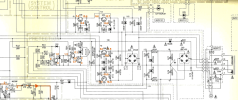
Yeah, that part of the power supply is relay activated, assumed the amp was powering/lighting up okThere might be a circuit that keeps that tranny off until another circuit is engaged
7 & 8 = 2.8 ohmWith amp powered off/unplugged
Measure resistance between pins 7&8 then 8&10 then 7&10
8 & 10 = 3.9 ohm
7 & 10 = 2.9 ohm
Solder is solid.
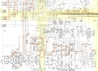

AgreeLooks like there is a relay RY2 that needs to switch on to allow the AC to get to the Tranny,
Nothing OL so windings ok, odd that 8&10 > 7&8 maybe the tap/join...7 & 8 = 2.8 ohm
8 & 10 = 3.9 ohm
7 & 10 = 2.9 ohm
With the unit powered via DBT gadget and the power switched on it goes into a loop: DBT off, RY2 clicks once, DBT light goes on, back to DBT off. The fuse stays intact. Without the DBT it'll most likely blow the fuse. So it probably was open during my most recent measurements on the trans pins. I am sorry, I didn't check it before doing the measurements. That may be the reason I got all zeros on pins 7,8,9,10. I didn't notice when it flashed as I always look at the LCD display to see if the unit goes on. And the LCD lights up even with the open fuse.Looks like there is a relay RY2 that needs to switch on to allow the AC to get to the Tranny, Am I correct @mbz?
Also Check Fuse F1 *42 , its on the right side of the attached schematic .
Attachments
Last edited:
Slightly confused, not sure why the focus on the pilot lamp.
Power up on DBT(75W abouts) expect an initial flash then DBT to be near off. In this case there is no short so power up without dbt, relay click? audio?
If dbt remained slightly bright then plz mention, if dbt was bright then a short still exists and needs troubleshooting. Past posts indicate you have replaced the faulty output and driver transistors. Plz measure dc voltage one side of R178 to GND, repeat for other side R178. Repeat for R177 ie, do both sides.
Power up on DBT(75W abouts) expect an initial flash then DBT to be near off. In this case there is no short so power up without dbt, relay click? audio?
If dbt remained slightly bright then plz mention, if dbt was bright then a short still exists and needs troubleshooting. Past posts indicate you have replaced the faulty output and driver transistors. Plz measure dc voltage one side of R178 to GND, repeat for other side R178. Repeat for R177 ie, do both sides.
This is not just a simple pilot lamp. It back lights the LCD display. Without it it is impossible to see if the unit is off or on. It seems like there are two parallel power lines. Why do I say so? Because even with the fuse blown the LCD display works. It turns on, shows the changes when you push some buttons, e.g. input selector, radio presets... That is the reason I didn't notice that the fuse was open and did the measurements on the big transformer pins.
Now about the power test you mentioned above. Without the DBT when powered on the relay clicks once and the fuse burns out. The LCD still on. You can see the info on it if you shine some light on the back of it.
With the DBT it goes into the loop and the fuse stays closed and functional. The loop: DBT is off, RY2 clicks once, DBT light goes on to full output brightness (not just dimming), DBT goes off and that starts a new loop.
Now about the power test you mentioned above. Without the DBT when powered on the relay clicks once and the fuse burns out. The LCD still on. You can see the info on it if you shine some light on the back of it.
With the DBT it goes into the loop and the fuse stays closed and functional. The loop: DBT is off, RY2 clicks once, DBT light goes on to full output brightness (not just dimming), DBT goes off and that starts a new loop.
Haven't worked on the amp, is it possible to lift one leg or remove both R219, R220. The idea is to unload the power supply to some extent. Power should then go to the power amp stage. Bright DBT points to power amp fault.
Have you diode tested the output and driver transistors
What is the dc offset for each channel, measured between emitter resistors
Have you diode tested the output and driver transistors
What is the dc offset for each channel, measured between emitter resistors
Output transistors: 2 L-ch tested out of ckt, 2 R-ch replaced with the tested new ones.
Driver transistors: 2 L-ch not tested out of ckt, 2 R-ch replaced with the tested new ones.
Will check dc offset for each channel, measured between emitter resistors tomorrow morning. And will try to figure out how to do "lift one leg or remove both R219, R220".
The unit goes into the loop, does it matter for the measurements? So I try to remove R219 and R220, plug it in and turn on, then do the measurement of the dc offset if it doesn't cycle?
Driver transistors: 2 L-ch not tested out of ckt, 2 R-ch replaced with the tested new ones.
Will check dc offset for each channel, measured between emitter resistors tomorrow morning. And will try to figure out how to do "lift one leg or remove both R219, R220".
The unit goes into the loop, does it matter for the measurements? So I try to remove R219 and R220, plug it in and turn on, then do the measurement of the dc offset if it doesn't cycle?
Last edited:

What going on here?
Id remove and test all these components here, especially the 10uf 16 volt cap , the diode next to it and what ever that small black cube next to it.

Q40 ? and C181? hard to read as the schematic is blurred there. And the Zener diode.
Hell test all the part in this section.
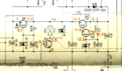
Id remove and test all these components here, especially the 10uf 16 volt cap , the diode next to it and what ever that small black cube next to it.
Q40 ? and C181? hard to read as the schematic is blurred there. And the Zener diode.
Hell test all the part in this section.
DBT is bright on power up, F1 blows when no DBT.What going on here?
Near short downstream those transformer pins 7-11.
Suggest lift R219, R220 to partly unload the psu, then power only to power amp (lightly cause).

Just a quick thought. I'd double check emitter resistors R190 & R188, since Q104 failed. I guess it's possible they're ok but, one or both of them always fail when an output shorts...in my experience.The emitter resistors R188, 190 show 0.4 ohm, all 4 of them, L and R channels.
Last edited:
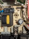
This cap is no good.No, it looks like that cap spilled its guts out the bottom.
Attachments
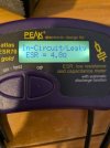
The four resistors R187-190 measure at 0.3 ohm.Just a quick thought. I'd double check emitter resistors R190 & R188, since Q104 failed. I guess it's possible they're ok but, one or both of them always fail when an output shorts...in my experience.
By now we found out that:
1 - there was a short on the main board and as a result two output transistors and and two drivers were swapped. The 4 emitter resistors seem to work;
2 - the Main Circuit Board (7) is not working well and two resistors are up for a swap;
3 - the Main Circuit Board (2) is not working well and at least one cap C182 (10uf 16 v) needs to be swapped. Other parts may need to be tested;
4 - DBT is bright on power up, F1 blows when no DBT. Need to lift one leg or remove both R219, R220 and observe what happens next.
Have I missed anything else?
1 - there was a short on the main board and as a result two output transistors and and two drivers were swapped. The 4 emitter resistors seem to work;
2 - the Main Circuit Board (7) is not working well and two resistors are up for a swap;
3 - the Main Circuit Board (2) is not working well and at least one cap C182 (10uf 16 v) needs to be swapped. Other parts may need to be tested;
4 - DBT is bright on power up, F1 blows when no DBT. Need to lift one leg or remove both R219, R220 and observe what happens next.
Have I missed anything else?
D25 zener.