• The move to the new server is done. There are some software and database maintenance updates in process. This has us passing the hat around to help out. We appreciate any donations. Seriously, even a dollar helps. The payment page may be found here - https://www.audiokarma.org/support.html

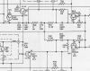
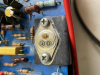
Yet another butchered 250

I'll probably try the 5089s. Still have to figure out why my bias is being dependant on the DC offset pot... Have checked my resistors and they're all testing okay.
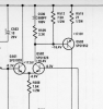
In my case I am getting flat 0.0V bias. What is puzzling to me is that the schematic explicitly states that there is 0V between the points we usually measure bias (across R531 and R532):

upload_2021-4-17_13-56-1.png

Which points are you using to measure bias?
 
In my case I am getting flat 0.0V bias. What is puzzling to me is that the schematic explicitly states that there is 0V between the points we usually measure bias (across R531 and R532):

View attachment 2198642

Which points are you using to measure bias?

So, I'm using the safety trick I learned on my 250M, you can measure your voltage that is used for bias on the collectors of Q507 and Q508, you should have something reasonably close to +.6v and -.6v.
It allows for testing without outputs installed
 
So, I'm using the safety trick I learned on my 250M, you can measure your voltage that is used for bias on the collectors of Q507 and Q508, you should have something reasonably close to +.6v and -.6v.
It allows for testing without outputs installed
This is interesting. I get exactly +0.6 and -0.6 at these points, but irrespective of what I set the bias trimmer to. These are also the green and yellow wires for the bias transistor.

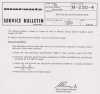
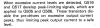
Here's the service bulletin that describes the procedure for the 250.Screen Shot 2020-01-09 at 7.06.17 PM.png
 
Last edited:
@goldswimmerb would you do me a big favor - using the diode function on your DMM could you please check the voltage across the base and emmiter of your epoxy transistor - from BLUE to YELLOW (everything turned off of course).
 
@goldswimmerb would you do me a big favor - using the diode function on your DMM could you please check the voltage across the base and emmiter of your epoxy transistor - from BLUE to YELLOW (everything turned off of course).
I hooked the epoxy Transistor up to the ATLAS DCA pro, which would catch if there was anything special inside that box, and it just said there was a standard Transistor in there with an HFE of 409.

What is interesting, is if I put my outputs in, I do get bias, and it is adjustable, however I don't really trust it given my voltages.

If you have +.6 and -.6 on those collectors then you should be OK.

For some reason my positive .6 is closer to .4-.5 and it is greatly affected by the DC offset adjustment potentiometer. My other half, the negative side has -.7 to 2v depending on where the DC offset adjustment pot is... By chance could you check for me if your +-.6 v change when you move the DC offset pot?

I'm curious whether it's an aspect of the design, or an issue regarding something else, like Transistor gain, as right now I have a mess of parts in there trying to figure out what helps/hurts my situation.

I'm hoping my assortment of Transistors arrives in the next week or two, so I can get this thing working, and be able to make a list in this thread as the "definitive" list of parts for the earlier 250s. I don't see many successful threads here on AK.

 
I am having the same dependency issue. I was able to get some 2mv of bias, but when I tried going up it started to drift upwards of 40mv and down. At the same time I could no longer get DC close to 0, it would get to -85mv at the clockwise end of the trimmer.

I wonder if I may need to convert this into a model B by throwing out the diode and the epoxy transistor and get readily available MPS6519 and MJE180. It won't look good on the board for sure.

Let me check the voltages at the collectors to see if I get the same behavior but it is very likely.
 
I am having the same dependency issue. I was able to get some 2mv of bias, but when I tried going up it started to drift upwards of 40mv and down. At the same time I could no longer get DC close to 0, it would get to -85mv at the clockwise end of the trimmer.

I wonder if I may need to convert this into a model B by throwing out the diode and the epoxy transistor and get readily available MPS6519 and MJE180. It won't look good on the board for sure.

Let me check the voltages at the collectors to see if I get the same behavior but it is very likely.

Thanks, if you get the same dependency issue it may be a quirk involving the design of the unit, or be component related. I've ordered a variety of Transistors to play with for the smaller guys. I think, in theory, one could modify in the MPSA6519 circuit externally. You'd just need to:
Lift the green wire, emitter of Transistor to board where the grn was, then put the green wire on the base, then run a 470ohm from emitter to collector, I think the diode gets replaced with a 560ohm, jumper across R556, add a 4.7k across one side of the 560 to the center pin of the bias pot, should be the same pin as the MJ's base, and I'd have to work out the rest since it'll involve cutting traces and getting the 2nd half of the pot actually hooked up
 
I already had to cut traces to add driver emitter resistors, it won't be a stretch to go all the way into 1200B. I basically implemented all changes in the addendum.

I have a newer 240 with the two bias transistors and it works really well and it is stable. I got the 1200 to play with might as well. Looks like a fun project.
 
I already had to cut traces to add driver emitter resistors, it won't be a stretch to go all the way into 1200B. I basically implemented all changes in the addendum.

I have a newer 240 with the two bias transistors and it works really well and it is stable. I got the 1200 to play with might as well. Looks like a fun project.

My only concern is that they changed a bit on the input side of the amp too, not sure how those changes stack up though
 
I've ordered an assortment of Transistors to try at various locations to see if maybe our lists for the later revisions are incompatible with the early ones for some reason. If that doesn't work I may wind up scanning the boards from my 250M that I have that works perfectly and getting some boards fabricated.
 
I've ordered an assortment of Transistors to try at various locations to see if maybe our lists for the later revisions are incompatible with the early ones for some reason. If that doesn't work I may wind up scanning the boards from my 250M that I have that works perfectly and getting some boards fabricated.
The input side on newer models have Q503 as a darlington with a Miller compensation capacitor instead of the SPS1952. There is also Q520 that seems to be a current source for the diff pair which is a good thing and may even be replaced by a real current source component (I did that for a 1120). But it seems that the real troublemaker is the bias section which is why I think they redesigned it. The diode/transistor design could indeed be flawed.

Please let me know if you do scan the newer boards - I would be very interested in building them from the ground up so if there is anything I can do to help let me know - like sharing the costs to get them fabricated. That would be better than cutting and kludging the old board into the new one.
 
The input side on newer models have Q503 as a darlington with a Miller compensation capacitor instead of the SPS1952. There is also Q520 that seems to be a current source for the diff pair which is a good thing and may even be replaced by a real current source component (I did that for a 1120). But it seems that the real troublemaker is the bias section which is why I think they redesigned it. The diode/transistor design could indeed be flawed.

Please let me know if you do scan the newer boards - I would be very interested in building them from the ground up so if there is anything I can do to help let me know - like sharing the costs to get them fabricated. That would be better than cutting and kludging the old board into the new one.

I'll know sometime probably in a week or two if I need to go that route, have a very nice assortment of Transistors on the way to try in various locations, it's likely these early models are very picky regarding HFE and Transistor characteristics.

I saw a thread on AK that someone had thrown an MPSA65 in for Q505, I may try that and see what happens. Can't make the amp any less functional.
 
If you do don't forget to add the 5pf cap for stability. A MLCC cap should do.
 
If you do don't forget to add the 5pf cap for stability. A MLCC cap should do.
Well, the interesting thing was Q505 is originally a 2N4125, usually replaced by a 2N3906. So that's why I figured I would try since I have some spare PNP darlingtons playing around a bit.
 
Well, the interesting thing was Q505 is originally a 2N4125, usually replaced by a 2N3906. So that's why I figured I would try since I have some spare PNP darlingtons playing around a bit.
Just to make sure - it isn't Q505, rather Q503:

upload_2021-4-18_11-55-7.png

Q503 is the "inverter" that is MPSA65 darlington in newer models:

upload_2021-4-18_11-56-8.png
 
My understanding of what does what in an amp is still a bit flakey, what is Q505 resposnible for? Current source?
Q505 and Q506 work with Q516 and Q517 respectively to limit the power output.

upload_2021-4-18_12-20-32.png

I ordered both 2N4125 and 2N4123 I should be getting them next week.
 
tempImageVmnbUP.png Following with interest as I am currently working on a 240 (with darlington inverter). I'm having issues with random DC offset fluctuations. I have replaced the diff pair, predrivers , outputs and the darlington as some were bad or out of spec Hfe-wise. I suspect the drivers (what's left?) but the batch of mj15030/31 I ordered are too far apart in Hfe to use. I swapped drivers from the good channel but the pins on one of them were welded to the soldered in inserts and literally ripped the insert out of the board. Somehow I managed to fix that mess but the transistor is damaged. I had to pop the cap off and push the terminals back out of the transistor. It still works but........
 
Last edited:
@rich l that is terrible. Welding the pins to the sockets is inconceivable.

What worked for me was the 2SA1011/2SC2344 pair from Sanyo with pretty close hFE and very high fT (which some people don't seem to like because it may lead to oscillations - I didn't experience that). Very hard to find though.

Other possibilities:

SC5171/SA1930 ;Toshiba
SC2238/SC4793
2SA1837/2SC4793 Toshiba

I also tried the MJE's but they don't work, and as you mention they are too far apart in hFE and caused the fluctuations you mention that in my case would show as hiss on the speakers and in some cases take it to protection with rails voltage at the output.
 
Back
Top Bottom