• The move to the new server is done. There are some software and database maintenance updates in process. This has us passing the hat around to help out. We appreciate any donations. Seriously, even a dollar helps. The payment page may be found here - https://www.audiokarma.org/support.html

Yet Another Maggie Rebuild: 185AA

BrassTeacher

Uncurable Tweaker
It's been awhile since I've posted...

Anyhow, I'm about to start a rebuild on a 185AA. I've just completed an 8802 that turned out well, but other than changing the value of the cathode bias resistor and a few cap values, I made no changes to the topology at all.

With this 185AA, I'd like to try something different, and use a Cathodyne/Concertina polarity inverter. (The term "phase splitter" is a pet peeve of mine, because it does neither in reality). I'm about to start stripping down the chassis to the bare metal, because this one appears to be Cadmium-plated, so I'm going to put a few coats of paint over it.
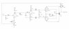
While that is being done, I'd like to post the schematic I've drawn up that I plan to use. Please feel free to critique/shoot holes in the design. It's been awhile, other than the 8802, since I've delved deeply into a tube amp, and I'm trying to relearn a few things. This particular design, since I suck at Ohm's Law calculations, is based heavily on recent reading. The gain stage is the original Maggie voltage gain stage, as is the output stage. The cathodyne/concertina comes from some of my readings (read: stolen from) The ValveWizard site.
The original power supply design will be used, except for dropping the last stage used for the 7025 phono amp. Also, all the original transformers will be retained for this build, assuming my cut-and-splice design doesn't blow up.
Anyhow, the schematic (have at it, gang):

334528842_1552293395258148_1455367172563709258_n.jpg


[EDIT]: One of the things I'd like to hear about is how to manage the two 12AX7 tubes. I can see the possible disadvantage of putting the gain stage and polarity inverter in the same tube, due to the 100V difference between the plates of each triode, but I can also see the possible disadvantage of putting the two gain stages in the same tube and the polarity inverter/driver in the other tube. The Dynaco ST-70 gets away with a voltage differential on the plates in the 7199, so maybe that isn't as big a deal as I think. Discuss among yourselves ...
 

Attachments

Last edited:
Register to hide this ad
Quick observation for now -- you will need to at least double the value of your output stage cathode bias resistor. At 120 Ohms, the output tubes will be severely under biased and.cause very high plate dissipation levels. Consider a value more on the order of 270 Ohms or so.

Good luck with your project!

Dave
 
Quick observation for now -- you will need to at least double the value of your output stage cathode bias resistor. At 120 Ohms, the output tubes will be severely under biased and.cause very high plate dissipation levels. Consider a value more on the order of 270 Ohms or so.

Good luck with your project!

Dave

Hmm, the original cathode bias resistor was 125R. Will give 270R a go though. OH, WAIT! I forgot to put the in arrow that says "To other channel" from the cathodes! I am going to keep the original layout of all four outputs sharing the same cathode bias resistor and cap...
 
So random thoughts in no specific order
Maybe consider direct coupled voltage amp to inverter. If not, have a close look at the rc time constant between the stages. Its different by a factor of 2, may need to be more for better LF stability.

Lots of amps did a voltage amp and split load inverter in a single 12ax7 with no issues. Lead routing to do one tube as amp for both and one as inverter for both will be messy and I suspect it would cause issues with crosstalk.

The 1nf to ground at the voltage amp cathode will boost the highs, possibly not a good thing.
 
So random thoughts in no specific order
Maybe consider direct coupled voltage amp to inverter. If not, have a close look at the rc time constant between the stages. Its different by a factor of 2, may need to be more for better LF stability.

Lots of amps did a voltage amp and split load inverter in a single 12ax7 with no issues. Lead routing to do one tube as amp for both and one as inverter for both will be messy and I suspect it would cause issues with crosstalk.

The 1nf to ground at the voltage amp cathode will boost the highs, possibly not a good thing.

Thanks for the input! I may indeed consider the direct coupling. I'll check voltages at the top and bottom of the split load inverter (Thanks, I couldn't remember the other term for it) with no signal after the build to make sure there isn't a huge discrepancy. I'd rather not have to add a DC balance pot to the circuit.

As for crosstalk, I was weighing the plate voltage difference against the crosstalk possibility. So, you're the second vote for putting amp and cathodyne on the same tube, the ST-70 schematic was the first vote!

The 1nF cap on the cathode of the voltage amp was part of the original design. Perhaps it was there to compensate for the high frequency speaker driver Magnavox used? Gordon: If you are reading this, please let me know if this is the case. Also, I want you to give a listen to the 8802 I just finished!
 
Fisher and Sherwood both did amps with that setup using a 12ax7, didn't seem to be any issues.

The stock response is usually kind of goofy but it probably did work with the drivers and other electronics in the cabinet. I've been fooling with a 197 and it looks more like a roller coaster than a proper amplifier.
 
Ok, so...
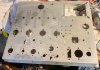
Today was supposed to be chassis tear down day, and still may be. This one will have everything removed, and have the chassis cleaned well enough to accept a couple coats of paint. I'm pretty sure this chassis is Cadmium-plated, especially after looking at it in sunlight. (Note the yellow-ish discoloration)

334788023_525432282841083_1716723264843987428_n.jpg


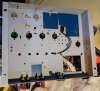
Now, if you're wondering why I've got it outside, it's not just for better photo taking. When I flipped it over inside, I finally knew what a color blind person felt like, because color differentiation of the cloth wires was difficult due to aging. So, when I got it outside, there were a few surprises...

330457366_496539589156467_6430736338164771094_n.jpg


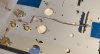
And here's a close-up of the biggest surprise:

334818857_762621148779471_8884333174423004745_n.jpg


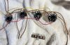
There are two Red/Yellow wires coming off the power transformer, and both go to the rectifier. Then, the almost plain yellow one with a couple orangish-brown flecks? That's the HV center tap, and I could only be sure after I moved the ceramic cap out of the way (don't worry, I have a replacement) to see it tied to a ground post. Those two orange wires? They're supposed to be brown. Also, since the output transformer wires are now difficult to distinguish color, drilling out all those rivets is postponed until I can find some adequate shi... uhm, stuff to label all the wires with :mad:
 
Thanks for the input! I may indeed consider the direct coupling. I'll check voltages at the top and bottom of the split load inverter (Thanks, I couldn't remember the other term for it) with no signal after the build to make sure there isn't a huge discrepancy. I'd rather not have to add a DC balance pot to the circuit.

As for crosstalk, I was weighing the plate voltage difference against the crosstalk possibility. So, you're the second vote for putting amp and cathodyne on the same tube, the ST-70 schematic was the first vote!

The 1nF cap on the cathode of the voltage amp was part of the original design. Perhaps it was there to compensate for the high frequency speaker driver Magnavox used? Gordon: If you are reading this, please let me know if this is the case. Also, I want you to give a listen to the 8802 I just finished!

The 1nf cap on the input tube cathode is, IIRC, an EQ cap. I always just deleted that.

Regards,
Gordon.
 
Progress has been made. Revised schematic:

Maggie 185AA DET.jpg

Chassis was stripped to the bare metal, the underside primed, surplus holes covered with circuit board material held in place by gorilla glue, and new hardware added:

IMG_2091.jpeg
IMG_2098.jpeg
 
More progress:

Chassis painted on outside (forgot to take pic earlier, so here's one after all hardware in place). This is Rustoleum Hammered Copper paint,
I'm still getting the hang of applying it correctly:

IMG_2111.jpeg

I decided to experiment with a ground bus and lift the circuit ground from the chassis completely. I will ground the chassis to the ground connector on the IEC power inlet. If I'm unhappy with the result, I left one chassis ground pin in place so I can ground the bus to the chassis if necessary, and will disconnect the earth ground on the IEC inlet:

IMG_2101.jpeg

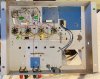
Voltage amp and cathodyne circuitry complete. I should have taken a photo from a lower angle, there is more vertical separation of components than it appears in this photo. It turned out to be quite the complex 3D structure. I arranged everything in as many right angles as I could to avoid as much stray capacitance and inductance as possible. Also, I bent and arranged component leads to make the structure as self-supporting s possible. It is far stronger and stiffer than it looks, and nothing bounces around :

IMG_2103.jpeg
 
Even more progress:

I recycled/reused the output tube sockets and wiring. I cleaned off socket pins that will be reconnected and terminal strip lugs that I will be reusing. Those sponge-type sanding blocks make quick work of cleaning the terminal strips. Cleaning socket pins was a pain, I swear the factory must have used solder that was a half-inch in diameter. The solder sucker became clogged multiple times, and it's one of those big blue plastic ones:

IMG_2104.jpeg

Pro Tip:
Always be aware of where your schematic is relative to the soldering iron holder. You may/may not notice the slight difference in burning/hot metal smell at first:

IMG_2105.jpeg

Amp circuitry complete except for heater wiring, transformers, and power supply. I added a second copper bus perpendicular to the first one to make life easier when building the output section. By the way, the copper bus material is very small copper tubing, not thick copper wire. The tubing is far more stiff and self-supporting than wire would be. I did not have a 33uf cap for cathode bypass purposes, so I paralleled a 22uf and a 10uf (close enough). Yes, those are Nichicon Muse electrolytic capacitors. Why? They are what I had on hand. Plus, some "audio high grade" capacitors don't cost that much more than regular caps.The coupling caps are Vishay MKP1839 series polypropylene. They cost about the same as orange drops, if not a little cheaper, and are far easier to work with. They are available rated for either 400 or 630 Volts, and are available in 1% tolerance, even though these are 10%. I used these in a recent Maggie 8802 rebuild, and I was very pleased with the result:

IMG_2108.jpeg
 
@BrassTeacher

Thanks for sharing your project & progress

What was the status of the original tubes will they be utilized or are you going for new?

Will the chassis be stand alone or will you be adding a wooden base for decorative purposes?
 
@BrassTeacher

Thanks for sharing your project & progress

What was the status of the original tubes will they be utilized or are you going for new?

Will the chassis be stand alone or will you be adding a wooden base for decorative purposes?

If I can find where I put them, I'll use the original 12AX7s after I test them to see if they aren't too far off from each other or side-to-side. The original 6V6 are currently residing in the 8802 I just rebuilt. I've ordered a set of Reflektor 6P6S (6∏6C) to try out in this one. If I don't like them, I'll swap them with the 8802. The 7025 will live in the "preamp tube" box for the time being

For looks, I'll be adding stained and polyurethaned wooden sides to the amp. Ok, partially for looks, mostly to have a place to screw on the feet...
 
Looking good so far! I used a quad of the Reflektor 6P6S's in an amp build. They sounded pretty nice.
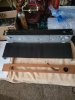
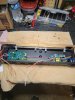
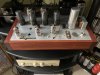
I like the color. I use it a lot in my builds. The latest is a nixie VU meter with bar graph tubes built into an old componant timer chassis. Most of the amps I've built from scratch is painted with the hammered copper.
 

Attachments

  • 20230323_115701.jpg
    20230323_115701.jpg
    111.6 KB · Views: 30
  • 20230315_100339.jpg
    20230315_100339.jpg
    142.4 KB · Views: 30
  • 20230319_140914.jpg
    20230319_140914.jpg
    155.2 KB · Views: 29
Here's a pix of mine which is mostly stock. I left the preamp circuit in and use an out board Blue velvet for volume control. Mates well with 50~60's jazz and vocals. I kept the original 6V6GT's in, but went for new Sovtek 12AX7LPS for the preamp tubes.
 

Attachments

  • 68616165718__828FC373-8240-4C3C-9F41-5E1147A642CE.JPEG
    68616165718__828FC373-8240-4C3C-9F41-5E1147A642CE.JPEG
    111.3 KB · Views: 34
Here's a pix of mine which is mostly stock. I left the preamp circuit in and use an out board Blue velvet for volume control. Mates well with 50~60's jazz and vocals. I kept the original 6V6GT's in, but went for new Sovtek 12AX7LPS for the preamp tubes.

Cool! The reason I paint all mine is "just in case" the chassis is cadmium-plated. I know the risk is low unless you're dry-sanding the things, but I may sell a couple of these off to fund other projects (and perhaps better output transformers), and I don't want someone's lawyer to get involved.

Ok, I gotta ask, what's the jumper wire on top do?
 
Back
Top Bottom