• The move to the new server is done. There are some software and database maintenance updates in process. This has us passing the hat around to help out. We appreciate any donations. Seriously, even a dollar helps. The payment page may be found here - https://www.audiokarma.org/support.html

Yet Another Maggie Rebuild: 185AA

what's the jumper wire on top do?

I really don't know. It was on the amp when I first bought it and the tech who added the binding posts, fuse and power switch left it in place. I think it's a lazy man's ground buss. I just left it there. My original intent was that I wanted to just hear what the amp sounded like first before I had any major modifications done. After the basics were done, it sounded good. So I left it alone. At some point, it will get a full overhaul. Generally I have been really impressed with some of these old console amps. With the right synergy, they are pretty enjoyable. (BTW, I really enjoyed your project. Your detail work is top notch. Let me know if you would like some projects :0)
 
I've played with a couple 175's and have a modified 9303 along with building a 8600 with DG's mods from scratch. They all sound pretty good.
It was a 175 that got me interested in getting into tube gear to begin with.
 
Taking a break before the "heater test" to share a few items that I hope are helpful:

First, a friendly reminder about the dangers of mains voltage wiring, even if you have been doing it for decades as I have -

About 15 years ago, I learned a lesson when working with mains circuitry that I had forgotten over the years, until today: NEVER plug in a piece of gear into the same power strip/circuit as your soldering iron! The first time this happened, I was working on an old ARP Axxe synthesizer. I was working on, and testing the power supply board (For those not familiar, the power transformer and mains connectors are part of the main PS circuit board. I had the synth and the soldering iron plugged into the same power strip. The later model Axxe has an IEC power connector, and the ground wire is connected only to the chassis. I powered the synth down, i.e, switched the power switch into the "off" position, and, thinking I was safe, picked up the power supply by lifting it up from the bottom of the board in my bare hand. It felt like someone hit me in the arm with a baseball bat. Yes, the outlet was wired correctly. Yes, I checked after I installed that outlet years before. The nearest uneducated guess I could make was that the soldering iron created a low-impedance bridge from Hot to Neutral, and since Neutral and ground eventually connect, WHAM.

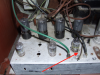
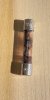
So, today after reinstalling the power transformer, I tack-soldered the hot side of the primary to one lead of the brown 6.3V heater coil, and the other brown lead to the hot pin on the IEC connector. I powered it up with only the rectifier heater and the HV lines connected to the rectifier socket, with no tube. The ground wire on the IEC connector was already connected to the chassis. Voltage readings went well, with 5.9VAC on the rectifier heater line, and some value I forget from one HV line to its center tap. Yes, the soldering iron and the amp were plugged into the same power strip, as I didn't want the iron to cool down (because I needed it for the next step). I was reaching to power the amp off, so I could swap ends of the brown heater leads and re-test, my forearm lights caught the edge of the chassis (it was painted even, but the paint must've been really thin there), and I got a moderately nasty tingle. I powered it off, swapped the leads, grabbed the voltmeter, and... ...nothing. This is what I found when I pulled the fuse out of the holder to check:
IMG_2123.jpeg

Gang, that WAS a 1.25 Amp fuse. I guess the strong tingle was only a tingle because of the brave sacrifice made by the fuse (RIP). So, after replacing the fuse as swapping the leads, I measured the rectifier heater voltage again, and came up with 5.2 VAC, so it was the correct way around, and after making the connections permanent, I brought the amp into the house to test it on a GFI outlet, to see if I had indeed screwed up the wiring. The GFI outlets I installed in the house will trip if you sneeze to hard near them, so I figured I would find out quickly. I plugged the amp in, with the power switch off, and all was well. I unplugged it, turned the power switch on, and then plugged the cord back in (did you REALLY think I was going to touch that amp given the circumstances?), and once again, all was well, and the fuse held, and I rechecked the voltage on the heater winding, with both my elbows WAY away from the chassis. When I test the heater circuit tomorrow, I'll put one lead of the meter into the ground terminal in a vacant outlet, and then probe the chassis. If there's even ONE volt of AC on that meter, that ground wire is coming out. And no, Gordon W, I didn't put the "death cap" back in! :p
 
Ok, previous post became rather long, so here's the rest:

If you don't yet have any of the following items, consider getting them, they make working on these things much more pleasant. First up -

IMG_2122.jpeg

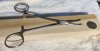
This little surgical tool, which I believe is for holding the needle when stitching things back up, is great for making "J hooks" on component leads or wires, and it gives you the ability to make them any size you want, especially if you're trying to keep them small. They also work great for closing the J hook off. The curved tip is ideal for working wires and leads into tight places, and for wrapping them around terminals or turrets. If I didn't have these, building the front end of this amp would've been extremely difficult, and it would've taken twice as long at it would with even fine tipped needlenose pliers. (Dime included for scale).

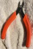
Next up, these neat flush cutters made by a company called "Xuron" (no affiliation). They sell this particular cutter in hobby stores for the purpose of cutting model railroad rails. Some of those rails are the equivalent of 12 gauge wire or slightly bigger, and are made of hardened nickel-silver or hardened plated steel. So, handling even thick component leads are no problem for these. In fact, they cut some of the ground terminals off this chassis with little effort. They are also sharp enough to cut paper, even after clipping thousands of leads.

IMG_2121.jpeg

More tomorrow...
 
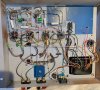
Today was heater test day! Everything has been installed except for the high voltage supply. If you're thinking the heater wires to the 12AX7 tubes look a bit skinny, they draw 0.3 Amps paralleled, and that solid-core wire is somewhere around 22-guage. If you're still thinking that's thin, look at the filament of a 1 Amp fuse, the wire is far thicker than that! :)

IMG_2124.jpeg

In case anyone is concerned with the feedback network just hanging off the terminal strip like that, don't be. That CDE silver-mica cap has really strong steel leads. If you press down on it, it springs back up like a tiny diving board. As an aside, I've seen some audiophiles complain about components having steel leads. I remember a big to-do being made over Nichicon going from tin-plated copper leads to steel leads on their audio-grade electrolytic caps. The big complaint - "The ferrous metal will generate an unwanted magnetic field". My response: Listen, Sparky, copper generates a magnetic field also, except copper is much better at it! I try not to dwell on the silliness too much, but when this one guy declared that a wire will conduct electricity much better in one direction than the other...

Anyhow, the heater test:

IMG_2125.jpeg

Passed with flying colors (and no sparks! :rflmao:)! The sharp-eyed will note that those are 12AT7 tubes in the front-end sockets. The heater current draw is the same as 12AX7, and no way was I going to plug in any of my good 12AX7s in that thing before it was tested!

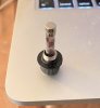
Next, checking for stray voltage on the chassis, and building in the HV supply. No, I'm not putting a can cap on it. I'm not paying upwards of $45 for a new can cap! Besides, it would block the view of the cool glow from the 5U4GB! Also, NO, the tubes aren't crooked, I had the phone really close to the amp when taking the pic.
 
Its lookng nice so far. I keep old weaker signal tubes on hand to use in new builds when testing.
I have some 6V6's, 6L6's, and a few other power tubes that I use when testing also. I started doing that after frying a brand new old stock 5V4 rectifier. :D
 
yeah half-shot tubes can still be useful. I have an assortment of bench test tubes that are good enough for a smoke test but not much else.
 
Ok, so today I was going to measure from ground (at the outlet) to the chassis to see if anything was leaking. Plugged in, power off, there was exactly one volt AC on the chassis. Powered on, and as soon as the probe touched the chassis:

IMG_2126.jpeg

Out came that ground wire. Oh yes, the amp was supported on wooden speaker cabinets, so it was insulated from the floor at least. Re-installed 1.25A fuse, no voltage on chassis without power. Upon power up, the fuse blew again, but it had melted slowly. Quite slowly in fact. as the filament was just drooping a bit. Ok, so maybe too much inrush current, even though the other 1.25A fuse held. Perhaps 1.25A fast-blow is just borderline. So, a 3A fast-blow goes in, no ground wire, and powered up. Measuring from outlet ground to chassis yielded 2.2VAC on the meter. The fuse held. Circuit still not grounded to chassis. Oh, after the first test failed, after taking out the ground wire, I measured from the chassis to EVERY lead coming out of the power transformer, checking for resistance on various scales of the meter (a BK 2707) from tens of ohms to 2M. All measured infinite resistance. Should I go back again and test on the 200M scale? Is 2.2VAC leaking to the chassis 2.2V too much? If so, I'd like suggestions before grounding the circuit to the chassis. Perhaps it will perform ok with the circuit not grounded to the chassis?

I'm not adding the HV supply until this is sorted, so please offer suggestions...

I may test the recently completed 8802 they same way to see how it measures up (pun intended), as it has played about 4 hours so far totally trouble-free.
 
wait, you removed the ground wire and the voltage on the chassis went away? Either your outlets are wired really wrong, or you didn't actually connect the ground pin to the chassis. Pic above sure looks like the center of the IEC to chassis, which last I checked was indeed the ground pin.

Might want to check the outlet wiring, I've seen some really screwed up stuff.

try a 2 amp slow-blow fuse
 
wait, you removed the ground wire and the voltage on the chassis went away?

Not exactly, there was still 2.2VAC showing on the meter...

or you didn't actually connect the ground pin to the chassis. Pic above sure looks like the center of the IEC to chassis, which last I checked was indeed the ground pin.

Might want to check the outlet wiring, I've seen some really screwed up stuff.

try a 2 amp slow-blow fuse

I checked after the build, had continuity to the center IEC pin to the chassis...

...going to try to find the outlet checker. The outlet is a GFI outlet, and it hasn't tripped yet. Outlet passes its test function.
 
Just happened to be looking through the Hammond service manual for the M-series organs, and happened across an entry that stated that anything above 4VAC when probing on any exposed metal part of the organ presented a shock hazard and needed to be corrected before returning to the customer...

So perhaps this amp is ok currently (again, pun intended)...
 
Couldn't find outlet checker, then I remembered I had a $100 DMM! At outlet, Ground to Neutral - 100mVAC, Hot to Ground - 121.4VAC, Hot to Neutral - 121.4VAC, so that outlet is just fine.

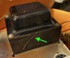
Now, I just this morning got in another 185AA to rebuild. Here is a photo of its power transformer, followed by a question -

IMG_2127.jpeg

The arrow is pointing to a thin, braided steel wire that is obviously attached to the bell and lying against the laminations. Is this some sort of drain wire to limit stray inductance? The transformer on the amp currently being built had one of these, but it wasn't lying against the laminations, but sticking out a bit. I was wondering why this random piece of wire was sticking out, and I clipped it off. Did I screw up?

Going ahead with HV supply installation, but again, any ideas on the 2.2V leakage, please chime in. It may be a normal thing...
 
Well, today I finished (so I thought) the build!

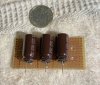
This replaced the can cap:

IMG_2133.jpeg

Yes, they are tiny, but they work well. These are Nichicon CY series caps, these particular ones are 39uF, 400V. I used them in the 8802 I recently finished. Highly recommended. If you wanted, these would be easy to hide inside the body of the old can.

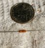
Now, this wee thing claims to be a 1 Watt resistor. The data sheet says the same thing. It is the size of an RN series 1/8 Watt resistor. We shall soon see, little one

IMG_2134.jpeg

The HV supply in place.

IMG_2136.jpeg

And the whole thing! The sharp-eyed will see that I have yet to wire the screens up. Somehow, just after I put the tubes back in, I remembered (if you knew me well, me remembering something like this before the disaster is a miracle).

IMG_2135.jpeg

After the screen mishap, I double-checked ALL the wiring again, and took the continuity checker and made sure all the HV lines were connected.

Hooked up the sacrificial speakers (which turned out to be a good thing), put the tubes in, hooked my computer up to the input. And threw the power switch. Nothing. After all that double-checking, I forgot to plug it in...

Ok, take two - After plugging it in, I threw the power switch. The heaters came up, and from both channels came a small hum that gradually became louder, then SHRREEEEEEEEEEEEEEEEK. I was sitting right in front of the speakers, and it was loud enough to nearly make me lose control of my bladder. The output tubes were definitely clipping. Now, it this was an old analog synthesizer I was working on, I would want it to oscillate when powered up. Not in this case though.

I have not yet connected the ground bus to the ground terminal on the chassis, so that will be the first step in hopefully making it into an amplifier again. If not, I'll pull the B+ off the output transformers and screens, and use the scope to probe the signal path with the input jacks grounded. I doubt that will show anything, but you gotta start somewhere. If that finds nothing, I'll rig up a dummy load, hook up B+ to one channel only, and probe around quickly before something melts down. I may also try disconnecting the feedback networks to see if that helps isolate the problem. Also, any and all suggestions are welcome. The shriek was about 6.5 - 7.5 Khz in case anyone was wondering.

But first, I'm going to take a break and let my heart rate slow down...
 
I bet your plate leads are reversed or your feedback is taken from the opposite end of the OPT secondary which makes feedback positive vs. negative.
When capacitors are connected in series, it’s good practice to use stabilization resistors across each cap. That makes them behave together as one and provides safe bleeding when power is turned off.
 
I bet your plate leads are reversed or your feedback is taken from the opposite end of the OPT secondary which makes feedback positive vs. negative.
When capacitors are connected in series, it’s good practice to use stabilization resistors across each cap. That makes them behave together as one and provides safe bleeding when power is turned off.

Will look at plate leads, thanks.

There are no series-connected caps, all are parallel. Feedback networks both taken from the green leads of the output transformers, so that is correct at least.
 
Back
Top Bottom