• Please note that Audiokarma will be offline briefly for updates early on Monday morning, September 28th.

Yet Another Maggie Rebuild: 185AA

Unhook it from the output tube cathode and sub in a voltage divider instead. Set it for around 50v and it should be happy enough. No tube section will be more than 50v h-k which is well within limits.

Still though, if that's the issue, it will go away if the 12ax7 is pulled
 
Still though, if that's the issue, it will go away if the 12ax7 is pulled

Ok, tried this again, here's the weird part:
With the 12AX7 in place, it hums fairly loud until the HV comes up, then quietens down quite a bit (like down to 1/3 to 1/4 as loud as it starts), I assume as the filter caps charge up.

Pulling both 12AX7 out, it starts with the same amount of fairly loud hum, but it doesn't get softer. So, there's obviously something going on in the output section. That said, the output section is almost unchanged from the original. I think I'm going to start building the other 185AA, add the cathodyne circuit, but keep the original chassis grounding points that are spread out all over the amp. If that works, I'll start all over again with this one going back to multiple grounds...

I'm going to add the voltage divider no matter what. Thanks for the advice on where to attach it.
 
try moving the speaker ground connection away from the spot the power supply grounds tie to and land it up by the 12ax7 cathode resistor connection. I'm wondering if maybe its picking up hum from that.

another thought, pull the rectifier tube and see if it still hums. If it does, you've got some sort of induced field problem.
 
try moving the speaker ground connection away from the spot the power supply grounds tie to and land it up by the 12ax7 cathode resistor connection. I'm wondering if maybe its picking up hum from that.

another thought, pull the rectifier tube and see if it still hums. If it does, you've got some sort of induced field problem.

Just the speaker grounds, not the OPT grounds, correct?

Just tried with no rectifier tube. Dead silent.
 
try moving the speaker ground connection away from the spot the power supply grounds tie to and land it up by the 12ax7 cathode resistor connection. I'm wondering if maybe its picking up hum from that.

Per my suggestion back at post 48. The feed back is subject to the currents circulating in the chassis. The common/ground side of the feedback needs to be connected directly to the bottom of the cathode resistor at the input for minimum noise pickup. This isn't likely your only problem but if you want a quiet amp, all issues have to be considered.
 
^^ exactly

normally I ground the output trafo right to the speaker jack. The ground from speaker jack to the rest of the circuit shouldn't go somewhere with noise, up close to the input tube should be quiet.


so no noise with no rectifier means its not an induced hum field, at least now there isn't concern about something funky with the transformer or their physical positioning.
 
seems too obvious to me , so I'm probably missing something , but are the gray and blue twisted pair coming from the 6v6 to the 12ax7 heater wires? And if they are , aren't they kinda close to the coupling caps? , actually running parallel with them?
 
aren't they kinda close to the coupling caps? , actually running parallel with them?

They are separated vertically by more than an inch.

I'll move speaker grounds to the ground terminal at the input as soon as I find my reading glasses. Same goes with the voltage divider to elevate the heaters.
 
Today's update:

Hum almost gone! It hums a wee bit, less than 1/3 where it was last time, and drops to very, very little hum after the filter caps charge. In fact, about the time the hum started fading, it was softer than the airplane flying outside (bug smasher) that was at least 3 miles away. That's with me about 2 feet away from the speakers.

Voltage divider has been added, and measured about 65VDC with no load (rectifier plugged in only), so it should be good. I may flip it over with all the tubes in and measure again just out of curiosity, but the ratio should give it about 51VDC when loaded. OPT grounds moved directly to speaker jacks without going to HV ground first, and feedback return grounded at input.

Since, sometimes unfortunately, I am a perfectionist, there are a couple more things I want to do. Currently there is no filter cap on B+ right at the cathodyne like there is at the AF side of the tubes. Can't remember who suggested it, but I'll move the bodies of the input resistors right at the tube socket, and it I can find mr roll of 1/4" copper tape, I'll shield it also. I used to be almost fanatical about shielding, especially when I built a solid-state preamp of my own design. Every bit of signal-carrying wire in that thing was wrapped in that copper tape and then the shields all grounded in the same place. It turned out to be a great-sounding (basically no sound of its own at all), and due to the shielding and being battery powered it was eerily silent (Ask Gordon W about it, he got to hear it on many occasions at the shop). Come to think of it, on the next 185AA build, I may shield all the signal lines right up to the body of the coupling caps going to the output tubes, as well as the feedback and feedback ground return lines.

Now, one thing I would like to know if someone can explain or figure it out:
After looking at my first schematic, someone asked dgillespie why there were no grid stopper resistors on the output tubes. I didn't put any there because the original did not, but after digging through the schematics for the next few projects and repairs coming up, they all have grid stoppers. The 185AA, as well as the 8802 I recently completed, do not have them. Is this something a 6V6 can just get away with? Or, was this a matter of the bean-counters at Magnavox trying to save 1.5 cents (at modern prices) on the parts cost of the amp because it would work without it?
 
probably was just an economy move. You can add them with no penalty but its probably not going to fix any problems that aren't there either. They are mostly there to limit bandwidth of the amp so it can't become a radio transmitter. Likely was determined it wasn't prone to it, so no point in spending the extra few pennies per unit. My 9300 and 197 didn't and don't have them either. The AMP-150 has half a set. Its PPP 6v6, there are 100 ohm resistors between the grids of the parallel tubes, but nothing between the coupling cap and the tubes. Nothing on the single ended 6v6 treble amp.

they are generally considered a good practice sort of thing to install, but its not absolutely necessary.
 
Thanks, gadget73. So, basically both my guesses were correct, doesn't need it, saved $$.

Since the last post, I hooked the computer to it and played some music (full .aif files, no compressed stuff for me!). With the hum almost gone, I'm extremely pleased with how it's sounding. I listened to a couple tracks, was surprised at the level of detail and dynamics, so I shut it down and plugged in the nearly perfectly-matched set of 6∏6C (6P6S) output tubes I got from Bulgaria yesterday. It wasn't a night-and-day difference between them and the Magnavox-branded 6V6 that were original to this amp (They tested well also), but they are better enough that I will not hesitate to get more, especially given the price.

I'm pleased enough so far that I just may go back in to the 8802 and delete the paraphrase inverter and replace it with a cathodyne, it makes a huge difference all the way around
 
Tried my last 2 tricks, hum unchanged.

Here's what's driving me nuts: Measuring AC voltage across speaker terminals - 0V. Measuring frequency across speaker terminals - 0Hz. The readings are the same measuring from the input ground to the HV grounding point. 0V, 0Hz. Input ground to + speaker terminal - 0V, 0Hz. Mind you, this is with AC sensitivity at 2V, and frequency meter sensitivity at 1V. Changing ranges just moves the decimal point. The meter says I shouldn't be hearing anything. Then, I go to probe elsewhere, I touch the + probe to the input grounding point, the other probe is still in my hand. When the + probe touched the grounding point, a small crackle came from the speakers. ???. Now, I'm sitting on carpet, the other probe in my hand, not touching anything, and the input ground reads 6.1VAC, 60Hz.

Now, I know if I'm in the garage and touch the oscilloscope probe with my finger, without me grounded to the scope, it does the same basic thing. Actually, any time I've touched a scope probe with my finger, anywhere, it does the same thing.

Maybe I'm just stupid...
 
the meter will pick up random things when not connected to anything at both ends. I wouldn't read too much into that.

Fair bet its not sensitive enough to really tell you whats going on. Scope across the output will though. Its probably in the millivolts range.

Is this with the input jacks shorted? Amps are prone to picking up hum when just sitting there not plugged in to anything. An RCA plug with a wire from center terminal to shield does a nice job to stop that.


also did we ever establish how well matched the output tubes are? If I didn't mention this before, current imbalance there will cause hum. Grounding the grids of the 6v6 tubes will make it quiet if the hum is coming from before the 6v6, if nothing changes its probably mismatched tubes.
 
the meter will pick up random things when not connected to anything at both ends. I wouldn't read too much into that.

Fair bet its not sensitive enough to really tell you whats going on. Scope across the output will though. Its probably in the millivolts range.

Is this with the input jacks shorted? Amps are prone to picking up hum when just sitting there not plugged in to anything. An RCA plug with a wire from center terminal to shield does a nice job to stop that.


also did we ever establish how well matched the output tubes are? If I didn't mention this before, current imbalance there will cause hum. Grounding the grids of the 6v6 tubes will make it quiet if the hum is coming from before the 6v6, if nothing changes its probably mismatched tubes.

Going backwards:
Yes, the original 6V6, and the set of 6π6C (6P6S) I've been using in it are well-matched, especially the 6π6C.

Inputs not shorted (yeah, I know, I should've)

'scope already in living room (Shhh), I'll rig it up later...

In the meantime, I moved the amp to my normal listening setup, and used one pair of the good speakers, KEF Reference 101 (not 101/2). Different outlet, and the KEFs are a bit less sensitive than the sacrificial Polk Audio T15 (Hey, I only paid $5 for them), 81dB vs 89dB. Different outlet and different speakers, and them hum is imperceptible more than 2 feet away, and you have to get within 1 foot of the speaker to hear it. So, I may have been chasing a ghost. All voltages are either dead on, or well within tolerances. Also, after the amp plays for about 6-10 minutes, the hum gets softer, but then again that could be because of the difference of listening to nothing but hum and the change of volume perception after listening to music for 10 minutes. Could be a bit of both. I once was lucky enough to have a Siemens CCa to use in the Counterpoint SA-1000 preamp I once owned, and that tube was noisier than all the other 6JD8/ECC88 that I had, but once it had time to truly get to operating temperature it was far quieter than any of them. So that could be happening here. The 12AX7 tubes I am using are Amperex Bugle Boys, that test well. As an aside, the label says "Amperex", but the top of the glass, and the heater flash at power-up screams "Mullard". They don't have Mullard codes tho...
 
Ok, time to declare victory!! Yes, there is still a barely perceptible hum if you put your ear 1 foot away from the speaker.

Two additional things were done. I elevated the DC offset on the heaters from 49.9V to 54V. Since it was the output stage that seemed to be the most grumpy, I decided to add some extra decoupling on one output tube from each channel, right on Pin 4 of the socket (Grid 2 or screen, whichever you want to call it), to the HV grounding point. I used a polypropylene cap in each spot, 4.7uF, 450V

I had originally planned to build this one and sell it to build up some extra funds to buy more parts, tubes, and amps to rebuild, and/or stuff to build a few from scratch. However, given all the pain and suffering this one has put me through, I don't think I can part with it now. Besides, it really sounds very, very good after the last tweaking I just did.

I have another of these to build, but I think I'll do these three W4-AM sitting around first...

A HUGE thanks to everyone who contributed and helped me re-learn, as well as learn new things, about working on this type gear. I may post a photo of the underside so you guys can check it against where I started, as long as you promise not to laugh at the spaghetti-bowl it has become...
 
One final update on this one, then I'll move on. I have another of these to build, plus four W4-AM to get to...

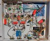
Anyway, here's the final version:

IMG_2157.jpeg

On the bottom side, all four output tubes have a 4.7µF cap as close to the screen/grid 2 pin as I could manage. The cathodyne has an additional 22µF right where the B+ line splits to each tube. On top, which does not have a current photo, I have a closely-matched set of Soviet-era Reflektor 6∏6C (6N6S) output tubes. These sound amazing after an adequate warm-up time. However, with these in place, the hum is a teeny bit louder, but not much. I suspect the extra load on the heater supply is showing up in this case. I know the power transformer does get warm with these tubes in, but certainly not above 100º. With the 6V6GT outputs in, it remains at room temperature.

So, the next one of these, which I may or may not document in a new thread, will have a grounding scheme closer to the original, using most of the original grounding tabs, and DC heaters. Instead of using the additional 6.3V winding as a bucking winding, I'll use one for the output tubes (the line originally intended for the amp), and the other for the input tubes, which is the line intended for the front end of the console. I may also recalculate to dropping resistor on the B+ line to lower the voltage on the AF amp side of each 12AX7. If all those work out well, I may go back into this one and at least add the DC heaters.

Again, this thing sounds really good (Nowhere near a Citation II or VAC Phi Beta), is fun to listen to, and it drives my pair of KEF 104/2 really well, and more than loud enough for me!
 
Ok, yes, I said I'd move on in the above post, but today I decided to try a good pair of closely-matched smooth-plate Telefunken 12AX7 (that I found messing around in the workshop yesterday). The results were better than the generic 12AX7 that I had in the amp, but not Earth-shattering. A little more clarity was evident though. One of my test tracks is the "Glory Days" track on the soundtrack to "The Incredibles". Played back on the computer from a non-compressed .aif file ripped bit-for-bit from the CD. One of the things I listen for has been missing on this amp, and that is a soft ride cymbal part that happens the first time the dynamic levels drop in the track (first time it gets softer). It still wasn't there on the Telefunkens. I figured it was time for me to resurrect my battery-powered preamp and try playing it through that. I assumed the level of drive at the low-end of the dynamic spectrum just wasn't enough from computer to input tube.
Then, I looked up at a pair of generic 12AT7 I had sitting on a shelf in the living room. Many years ago, I built a preamp based on a 12AX7 that sounded much better when I tried a 12AT7 in it. I thought, "Hmm, I wonder...". So, in the generic 12AT7 went (Ok, one was a Mullard, but it was horribly unbalanced. The other I believe was an RCA, the label had worn off but the tube number looked like RCA's mark).
The less-than-ideal12AT7s in this circuit absolutely SMOKED the good pair of Telefunken 12AX7. Like not even close. The effect was if I had been listening in the kitchen, then suddenly walked into the living room where the speakers are (There's no door between the two).
All of a sudden, my missing ride cymbal part was there, as well as a few other high-pitched percussion parts. So, out came the good pair of balanced Telefunken 12AT7 that I had on hand. Ride cymbal part was still there, but you could hear the musical shape better, since it was not played every note the same volume. I heard a few electric bass lines I had been missing, and you could hear the musicianship and style of all the musicians much better. It was totally missing with any version of 12AX7, I just hadn't noticed until the 12AT7 swap. Instead of hearing a really good lead trumpet player, you can tell that it is definitely Wayne Bergeron. He has a distinctive sound in the upper range.

So, long story short, give up on 12AX7 in this circuit. Get a good pair of 12AT7. Trust me.

Lastly, on today's episode of "It's Enough to Make a Grown Man Cry", we have this:

IMG_2232.jpeg

Pretty, aren't they? They appeared to have little to no use. After the success of 12AT7 in the amp, I started testing all the 12AT7 I had. These are all, of course, Amperex made by Mullard. They are ALL basically dead. :(. The best single triode measured 2900 (new is 4000 on the 800A), which isn't horrible, but the other side was 1200. All the other individual triodes came in between 1100 and 900 :(. Yes, tubes tested before and after had quite a few in the 3800/4000 range. I was so disgusted I didn't even put them back in their boxes, I'll use the boxes for other tubes that don't have them.

 
Back
Top Bottom