• The move to the new server is done. There are some software and database maintenance updates in process. This has us passing the hat around to help out. We appreciate any donations. Seriously, even a dollar helps. The payment page may be found here - https://www.audiokarma.org/support.html

Z19 Crossover

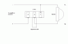
This drawing worked for me. There was one like it on each of my L Pad boxes, too. The artist's point of view was looking at the L Pad with the terminals up front and the shaft behind them, pointing down. It works the same as that other drawing, which is just flipped with the shaft facing up.
 

Attachments

  • 260-248d.gif
    260-248d.gif
    7.5 KB · Views: 147
This drawing worked for me. There was one like it on each of my L Pad boxes, too. The artist's point of view was looking at the L Pad with the terminals up front and the shaft behind them, pointing down. It works the same as that other drawing, which is just flipped with the shaft facing up.

So when looking at the l-pad from the front, #1 is on the right?
 
Yes, assuming the shaft is pointing down and the terminals are at the point closest to you. Why they don't just stamp numbers on them ....
 
Yes, assuming the shaft is pointing down and the terminals are at the point closest to you. Why they don't just stamp numbers on them ....

I think I get it. I am referring to looking at it from the front and you are looking at it pointing down. Either way the #1 is on the right.
I was wondering the same thing about numbering them.
I guess they think if you are going to use this product you should already know.
Kind of like working on my 6.8 F350, if you have to ask which is #10.....:D
 
My crossovers are complete.
I can't believe I went from nothing to new xo's! Thanks Zilch wherever you are.
Now, should I test these somehow before installing them?
DSC03618.jpg


DSC03619.jpg
 
Strong work, Ricoh! Those look great. I say you should just install those bad boys, fire them up one by one, gradually increasing the volume. What could possibly go wrong?

And of course post more pix!
 
Last edited:
Sweet!!!

Nice work. Zilch does some amazing stuff. I am listening to the Z mans version of the 4430 crossover (N3134) right now. Glad I am local and get to visit the 'lair' now and then.
Steve
 
Word! So at what L pad knob position is the response (at least theoretically) flat? I figure the midpoint, but wasn't sure ...
 
Word! So at what L pad knob position is the response (at least theoretically) flat? I figure the midpoint, but wasn't sure ...

Good question. Are there any measurements on Model 19s out there?

I am looking forward to remeasuring my Altecs w/ Z19s, since I have a better system now. I don't have Model 19s, however, but I will post LPAD positions with the graphs in case anyone has the same setup.

Btw, I recently heard a set of 19s for the first time (that I can remember) in Tokyo. They have a lot of Altec stuff there. : )

Subjectively, they were very similar to my 98448-Bs.
 
Interestingly, if you use the standard cover plate from Parts Express, the neutral position isn't marked, but I had thought it might be halfway across about a 270-degree arc:

260-250_L.jpg


But if you use the two-knob plate they sell, it's marked at about 80% of the way around:

260-274_L.jpg


Yet either way the L pad itself is the same. I used the two-knob plate and pushed the knob onto the shaft such that the halfway position on the L Pad appears at the "0" position on the plate.

But now I think that's wrong. It actually seems to depend upon the circuit design of the crossover, per this thread, which states that the full clockwise position runs the signal full strength, but suggests that a crossover designer may tweak the equalization to achieve a flatter response with some attenuation, at some other arbitrary point.

And now I just found Zilch's statement here: "LP1 is balance with LF, then set LP2 for VHF level."

So I guess, on the image below (posted by Zilch at page one of this thread):

attachment.php


Red line = LP1 at highest setting, LP2 at lowest setting.
Yellow = Both at highest settings.
Blue = LP1 at lowest setting, LP2 at highest setting.
Green = Both at lowest settings.

(That's just what I believe; I could be wrong.) But I can't tell where the woofer curve would be relative to the horn curve. In any event, if I'm right, then I should set LP2 (VHF) to its minimum position to flatten the horn as much as possible. Once it's flat, I should adjust LP1 (MF / volume) so that the horn and woofer seem to be about equally loud (maybe use my pink noise generator and spectrum analyzer apps on a pair of iPhones to help). Once I have LP1 set properly, I can monkey with LP2 to adjust the treble curve to preference.

 
Last edited:
[EDIT: Looks like I had actually L1 (MF) and L2 (VHF) assigned correctly; see further below.]
 
Last edited:
PPS

OK, I just turned off my sub, set the L Pads to their lowest points, then started adjusting them to where my iPhone frequency generator actually sounded fairly uniform across the spectrum. I did that first on the mid control, focusing on the range of maybe 800 - 2000 Hertz, then I tweaked the high control to bring up the highs a little. Last, I brought the sub back in, rolling it off at about 50 Hz.

And here's what I found: The L pads were set waaaaaaaaaaaaaaaaaaaaay too high previously. Now, the mids are set at only about 2 on a 10 scale, with the highs a little more. Before, they were both at 6 or so.

I think my sub was really tricking my ears into thinking the lower end was more flat. The lower end is much better now, with more bass from the 846Bs and the sub filling in just the very bottom.

Once I can steal my wife's iPhone for half an hour, I'll use one phone to run pink noise and the other to run a spectrum analyzer, although they're not calibrated so it's pretty crude.
 
Last edited:
Back
Top Bottom