• The move to the new server is done. There are some software and database maintenance updates in process. This has us passing the hat around to help out. We appreciate any donations. Seriously, even a dollar helps. The payment page may be found here - https://www.audiokarma.org/support.html

Zilch's AK Design Collaborative - Econowave Speaker

Another

Wayne,
Supposing one had a woofer of low efficiency as in my PM, accounting for a 24dB discrepancy between woofer and HF. I realize that is not ideal in terms of unmatched power compression. Anyway, since I can't use spice yet, I'm thinking I could attenuate at a value borrowed from your chart, and add more attenuation with an LPad following that. I'd get some adjustability and the splitter filter still sees the correct impedance.

EDIT: I guess it's not the right impedance if the circuit is not designed for the specific driver. OK. Back to square one...

Sorry for the confusion.
 
djnagle- if my EWs come out looking half as good as yours, I'll be happy. Nice stuff.

I've been trying to digest the information relating to L-pad use, padding, etc. but am suffering from a bit of conceptual gastric reflux... Does anyone see any problem in using a Yamaha NS-690 L-pad in the X-over? I have built the Kegger-design X-over as I will use HPM-100 woofers. I have both high and low controllers coming.

In another thread, I read some discussion concerning cabinet damping. It seems there are a couple of alternatives- polyfill, wool and fibregalss. I was thinking of using bog-standard fluffy fiberglass stapled to all interior surfaces, as I have plenty on hand. Any reason to consider alternatives?
 
Okay now that I have BA A200's to listen too I am not using my Advent/1's so seriously would the cabinets with the woofers in them be a good bass unit for the econowaves?

I would have to mount the EWG's on top of the cabinets as they are not wide enough for them inside. But this may be better anyway.

Does anyone think this would work or am I better off finding something much larger to try them with?

Cost/performance ratio to be considered.
 
Look at Keggers KPM100s. His horn is outside the box. He flipped the cab up side down so the woofer is up higher and set the horn on top so the horn and woof are very close. I can tell you from personal experience, his EWGs sound great. Cheers.
 
When you derived the attenuation values using spice for your Pi crossover, you calculated values specifically for either driver option. And so when you came up with values for the Econowave crossover, you must have looked at the Selenium driver specifically in Spice. Is that correct?

In other words, substituting another driver is not acceptable without running the numbers?

I thought some aspects of compensation in a compression driver were generic.

Actually, most aspects of compression drivers are generic. In fact, most aspects of CD horns or waveguides are too. I'm not talking about differences between horns that employ diffraction verses those that are radiused smoothly. That's a different matter entirely. I'm talking about power response, and what sets the overall shape of the response curve in a compression driver mounted on a constant directivity horn.

The bottom line is this: If you are using a CD horn or waveguide, there is only one transfer function you need to worry about. They all share basically the same one. That's why there is one curve for CD equalization. It is the conjugate of the power response of the driver.

When I first started doing this, I sort of assumed there would be more differences between drivers and horns. Different horns have different coverage angles, flare shapes and features. Different drivers have different diaphragm materials, motor structures, voice coil impedances and phase plugs. About the only thing that's the same is the exit aperature size.

But what I found was that the biggest difference is the voltage sensitivity. The driver's impedance plays a part and the horn's coverage angle plays a part. Once you know that, you're pretty much set.

There are many reasons for this. Each variable has a set of conditions that it describes. But they tend to act together. For example, if a horn provides constant directivity, then the SPL within the coverage angle tracks the power response of the driver. So the narower the angle, the higher the SPL within the pattern, but it is always the same shape as the response on a plane wave tube. So equalize that response and you have the correct response anywhere in the pattern, for any horn that provides reasonably uniform directivity.

There are a lot of things in the compression driver that can be variables. Change the amount of compression and bandwidth, efficiency and sensitivity changes. Different diaphragm materials and thicknesses mean potentially different mass rolloff and different breakup modes. Their phase plugs' ability to equalize path lengths and reduce front chamber volume can provide extended top end, but some designs rolloff sooner. Voice coil inductance sets another rolloff pole, basically marking the end of useable response.

But in the end, you'll notice all modern 1" exit compresion drivers act somewhat similarly, with mass rolloff starting around 4kHz. The biggest difference is behavior in breakup - some are well damped, others not. Most start around 8kHz, and some get real peaky above that. It can give some additional high end, but it can also make them sound shrill. Can't do much with that except choose compression drivers carefully. You don't want a compression driver with a lot of spikes in its response curve, because you can't do much with them. Beyond that, since mass rolloff happens around the same place in each driver, this means top-octave augmentation should start the same for each driver. About the only difference to design for is the impedance, which sets the voltage sensitivity.

That's why the R1/R2/C1 values I've used for years in my crossovers are the exact same values you should use in your crossovers, even though the horns and drivers are different. This is true of just about any driver on any CD horn.

 
It was odd, being such an A7 fan.....super big box w/cool flares, big 511B horn, altec fave, the 802 8g....yeah like this cheapass wave guide will compete! I'm so sure! Quite an eye opener it was, almost like an optical illusion! Zilch was right again! Altec is what it is, and I love it for that.

I have some strange obsession about vintage stuffs. May be modern technology has out done most of them. Jack's cheap Gold wood reported sound good and Dayton as well. I heard some good things about kappalites and deltalites. May be they will outdo vintage JBLs and Altecs? Nooo!:naughty:
 
Dennis,

Your ESS Waveguides are simply stunning. You went way out to come up with such a creative pair. Congratulations for a superb job. My hat is off to you. :yes:
 
Thanks Jack, they sound better than they look. If you notice in one of those shots, you can see my Imperials in the corners and they both fill the room equally. I just can't say enough about these things. Cheers.
 
OK, I've run the siumulations with Spice and found that you can use the exact same chart of values I use in my crossover. I guess I shouldn't be surprised, but it is indeed good news because now you have a chart to work from.

The only thing is, the nomenclature is different. In my schematic, R1 is the series attenuator, with C1 in shunt across it. R2 is the load resistor. You guys have R2 as the series attenuator, C3 in shunt across it and R1 is the load resistor.
Help me, now, I'm not seeing this.

Comparing the Pi document:

http://www.pispeakers.com/Speaker_Crossover.doc

with Jack's drawings:

http://audiokarma.org/forums/attachment.php?attachmentid=83308&d=1205870935

http://audiokarma.org/forums/attachment.php?attachmentid=90113&d=1210028233

R1 is the series attenuator in both cases, and R2 the load resistor, no? :dunno:

If you're looking at my Spice sim schematics, they are not definitive. That's just the order in which I drew the components, their designations being automatically assigned by the program:

http://audiokarma.org/forums/showthread.php?p=2142479#post2142479
 
I confirm what your seeing Zilch,

Wayne must have looked at your spice for R1, R2 not the schematics we've been using.
 
I'm working through the power resistor dissipation thing, and the revised table did not make sense; it's clear we are not on the same page here.... :no:
 
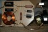
Crossovers done. These are the best crossover I've ever built. They are also the only crossovers I've ever built.
Waveguides been got. Just need to finish the cabs.
 

Attachments

  • コピー ~ DSC_0130.JPG
    コピー ~ DSC_0130.JPG
    92.5 KB · Views: 90
  • コピー ~ DSC_0132.JPG
    コピー ~ DSC_0132.JPG
    80.8 KB · Views: 76
If you're looking at my Spice sim schematics, they are not definitive. That's just the order in which I drew the components, their designations being automatically assigned by the program:

Yes, I was looking at your schematics. I thought they were what you guys were working from. I assumed you and Jack were in sync, and maintained the same nomenclature.

So use whatever nomenclature you decide on, and match it up with mine by circuit position to identify component values.
 
I have some strange obsession about vintage stuffs. May be modern technology has out done most of them. Jack's cheap Gold wood reported sound good and Dayton as well. I heard some good things about kappalites and deltalites. May be they will outdo vintage JBLs and Altecs? Nooo!:naughty:

If you havent already done so, have a look at Wayne's Pi site. He uses a lot of the Eminence drivers quite sucessfully. I've wondered why no one has tried those drivers in this project, ( woofers ) it seems like a natural for it, Wayne has put them through there paces already!
Obviously, I love the vintage also. I was listening down stairs last night to some FM, Mcintosh MR 67 tube tuner, Audio By VanAlstein Super Pas III pre amp, P-P 6550 amp based on a Mcintosh amp, and the Altec A7, 828 cabs, 416 8C, 802 8G and 511B horn. Very, very nice sounding, I love them. Many do, and yes they are outperformed by more modern pieces in some respects, but certainly not in the " imaginary gonadatrophic effect" department, the big Altecs are king there for sure!:thmbsp:


Russellc
 
Crossovers done. These are the best crossover I've ever built. They are also the only crossovers I've ever built.
Waveguides been got. Just need to finish the cabs.

Nice, and very fast work! How are the cabs coming along? include pics, I'm not quite up to speed tool wise to be building just yet. You are going to love this project and those speakers!

russellc
 
If you havent already done so, have a look at Wayne's Pi site. He uses a lot of the Eminence drivers quite sucessfully. I've wondered why no one has tried those drivers in this project, ( woofers ) it seems like a natural for it, Wayne has put them through there paces already!

Thanks for the mention. The four Pi loudspeaker is very similar to what you guys are doing here. That's why there is so much cross pollination in our crossovers. They are designed for the same purpose, and do fundamentally the same thing.

Eminence drivers are used in our less expensive models, JBL and B&C in the better stuff.

As an example, the four Pi and seven Pi models use JBL woofers and B&C tweeters in their best trim, Eminence in the budget versions.

Eminence woofers do sound nice, but they don't have shorting rings. The JBL's do.

The difference in the B&C compression driver is breakup is more smoothly damped. The PSD2002 sounds very good, reasonably smooth and nice sparkle. But the DE250 is noticably smoother and it has greater HF extension too.

The DE250 is a couple decibels higher in voltage sensitivity than the PSD2002, so the R1/R2 components are different, depending on the driver. It's 16/16 (-10dB) for the Eminence driver and 25/16 (-12dB) for the B&C.

 
Active crossover, Eq? Anyone

Wayne, or anyone else...chime in.

The cost of your 4pi crossover seems quite expensive with all the parts.

With cheap, quality, behringer gear, you can actively crossover the 2-way, and add an EQ for similar pricing (on ebay anyway).

Behringer cx2310 active crossover, with sub out. FBQ3102 or equivalent EQ. I have the DEQ2496 (but more expensive).

So, What is the advantage of a passive crossover versus electrical? If any.

I understand the obvious....not toting around expensive rack gear, or the requirement of biamping.

However, if, and I do...have all that stuff...which should I buy, passive, or go active.??

Here is a parts list from PE for reference on what I picked out on crossover parts. (about $140 on 2 crossovers)... Notice I picked out the Dayton 15" any comments? seems like an Eminence Omega 15 to me...

004-16 Yes Dayton DNR-16 16 Ohm 10W Precision Audio Grade Resistor $0.98 $15.68

019-020 Yes 8 Ohm 100W Non-Inductive Dummy Load Resistor $13.50 $27.00

027-424 Yes Dayton DMPC-6.8 6.8uF 250V Polypropylene Capacitor $2.79 $5.58

027-436 Yes Dayton DMPC-20 20uF 250V Polypropylene Capacitor $6.09 $36.54

027-458 Yes Dayton DFFC-0.47 0.47uF 400V By-Pass Capacitor $1.47 $5.88

295-080 Yes Dayton PF385-8 15" Cast Frame Driver 4" VC $140.00 $280.00

255-230 Yes Jantzen 0.50mH 18 AWG Air Core Inductor $6.60 $13.20

255-100 Yes Jantzen 1.0mH 15 AWG P-Core Inductor $9.42 $18.84

255-104 Yes Jantzen 1.5mH 15 AWG P-Core Inductor $10.84 $21.68

Subtotal: $424.40
 
I have no problem with the idea of using an active crossover, provided it is setup to deliver the same signal to the drivers. You'll gain several advantages when biamping. But the key is in the qualification, "provide the same signal to the drivers". I'm not sure you can do that with an inexpensive active setup. Further, I'm not sure that they use quality components. Cheap opamps have terrible zero-crossing distortion and slow slew rate. I'd rather not have those in the circuit.

When I develop a crossover, I use analysis tools that are well beyond what most DIY'ers want to take time to learn. I perform a lot of simulations and tests to get everything right, which takes a lot of time. Not only do I do on-axis measurements but also off-axis in both horizontal and vertical planes, impulse, step, harmonic distortion and intermodulation distortion. This is a pretty exhaustive battery of tests.

I'm not saying DIY'ers are incapable of this, far from it. I'm a DIY'er, and at first just provided plans for other DIY'ers. Now I provide kits too, but there is no obligation to buy. I still have a love of audio, and that's the main reason I do it. That's also what attracted me to this project, it's a bunch of guys walking the same path I have. That's the point, we're all DIY'ers here and I think what we're doing is better than 99% of the loudspeakers out there.

I will tell you this though: Optimizing a loudspeaker, while not difficult in principle, is somewhat time consuming. Most don't go the distance. Few even measure on axis and almost nobody measures off axis. Most don't even have the equipment to make useful measurements. So having the amplifiers and active crossover to do a biamp setup does not guarantee best results. If you aren't prepared to spend at lot of time doing the measurements, you'll probably be better off with the passive crossover that has been purpose designed for the loudspeaker.

Either way, get the best components you can. Don't skimp on the quality of parts you use. You don't have to get audiophile components, necessarily, but do buy propylene caps and large guage air-core coils. If you go the active route, use quality amplifier chips like those from Burr Brown.
 
capacitor question

Wayne,

Can Caps C3 and C4, the shunt caps in the low pass section, 20uf, can these caps be electrolytics, because they are not "in" the audio pathway.

I have heard many other crossover designers say this is acceptable.

It would save some money.

Parallel some electrolytics -027-340, which is 50 cents for one, so 1 dollar versus, 6 dollars. (5 dollars x 4 caps = 20 bucks).

Then again, 20 dollars worth risking?
Jake
 
Back
Top Bottom