• The move to the new server is done. There are some software and database maintenance updates in process. This has us passing the hat around to help out. We appreciate any donations. Seriously, even a dollar helps. The payment page may be found here - https://www.audiokarma.org/support.html

Zilch's AK Design Collaborative - Econowave Speaker

Hi,
Assuming I understood a fraction of what W.Parnham wrote/diagrammed,
I'm going to have to make adjustments in position of my woofer/hf driver,
as they do not line up nicely/neatly, per his diagram....My woofer sits
between 1"-2" more shallow, than the hf driver, measuring a center line
through the magnet positions,....So, my question is, Is there a preferred
recomend regarding this? IF, it is better to mount the woofer on the inside
of the front baffle, then I've got a lot more cutting to do,....Or moving the
waveguide horn forward, will eliminate a screen/cover, any thoughts?.......
Thanks for your time, T
Mr. Parham was careful to point out twice there that the optimum alignment may NOT coincide with physical alignment of the voice coils. I have found front-mounting both the waveguide and woofer on the same flat vertical baffle to be satisfactory with LE14A woofers. Skywave's initial determination was that the waveguide should be somewhat forward (or the woofer back) using 123A-1 woofers. You've really got to measure the driver behavior in the time domain to find the acoustic centers precisely, preferrably in the actual alignment. As Skywave is presently sorting out, other factors have a role in this, as well.

It's important to keep perspective, too, however. Not very many designers pay attention to this level of detail, though their results might be better if they did. Often, in common practice, it's just invert the HF driver phase and go with whichever sounds best.... :yes:
 
I will say this- given a lack of measurement equipment, mounting the speakers with the voice coils aligned will usually get pretty close. If anything, I usually would like to leave the horn driver voice coil a bit behind the woofer (ie, don't OVER correct it), as a default position. Seems to work at least about 80% of the time, correctly.

As Wayne and Zilch have mentioned, though, measuring it (the Altec method is a very good one, as it only requires a spectrum analyzer, which is a pretty easy tool to get, given how many computer-software-freeware type things are out there for that) is the way to go, if you want it exactly right...

Also, keep in mind, that you may want to adjust the alignment, to account for the listening position (ie, where the ears of the listener are) vs. the location of the drivers. In other words, if the listener is above the speaker and the horn is above the woofer, you might want to "set back" the horn a tad, to compensate for the difference in path length (you want the same "effective path length" from the driver acoustic center to the listener, from BOTH drivers, AT the preferred listening position). This is something I tend to do, frequently... it does seem to optimize things quite well, in most cases, though I have found a few, where it just didn't seem to help...

Regards,
Gordon.
 
Great post Wayne! A lot to absorb there to be sure, and this really underscores my need for more test equipment. Getting ready to move into a new house, which has way better room for speaker building/listening, but until
I sell the old one will be on a rather tight budget. Once that sucker sells I'm getting everything I need, well, within reason anyway. At least the DEQ 2496, microphone, and the 3400 crossover for starters.

I am really getting tired of flying blind, and this thread is really motivating me to get with it.:smoke:

Russellc
 
Null angles and vertical control

However, extrapolating from the AES graphic, though It seems counterintuitive, increasing the center to center spacing narrows the arc between nulls (given the same crossover point.) I hope I’ve determined that correctly.

That's right, the further apart the drivers are placed, the narrower the arc between nulls.

I was wondering if you think basic RTA capability could be used to determine vertical off axis response nulls? For example, after using the Altec method to determine correct horn fore/aft alignment, could I move my mic up or down to the assumed null point and check for a notch or actually a falloff at the crossover frequency? If this is visible and reliable, driver center to center spacing could be fine tuned in this manner, checking for symmetry both above and below at null axis positions.

If you're using non-gated measurements, it's best to look for null angles outdoors. Lay the speaker on its back and use a boom or something (acoustically small) to get the microhone over the speaker a few feet. You'll be able to see the reduction in amplitude caused by the nulls.

If you have equipment that allows you to setup gating, you can do pseudo-anechoic measurements indoors. This won't let you see the bass, but you can see what's happening in the crossover region with a gated measurement.

But if you're measuring with an RTA, do it outdoors so you won't see notches from boundary reflections.

For all these measurements I assume the microphone should reference the center point between the two drivers, not the horn center, as the axis of measurement.

If you position the microphone on-axis with the horn, it is closer to the horn than the midwoofer. The midwoofer is off-axis at an angle but the tweeter is not.

Best to position the microphone far enough away that both woofer and tweeter are as close to being on-axis as possible. The trade-off is the further away you get, the more noise you have to overcome by driving the speaker louder.

For a speaker like this, I'd say two meters is a minimum.

Another assumption I hold: As the listener moves away from the centerline of maximum phase reinforcement vertically between drivers, phase cancellation increases progressively to a maximum at the null. Beyond that, reinforcement may begin if the null has not been properly aligned with the end of the dispersion pattern at crossover frequency. So it’s important to know what the dispersion really is at crossover, and have a midwoofer which is very close in this characteristic.

On-axis, the sound sources are coherent and completely in-phase.

As you move off-axis in the horizontal plane, the same thing holds true. The only thing that changes response through horizontal movement is the directivity of the sound sources. Since they're matched through the crossover range, what you see is nearly omnidirectional radiation gradually narrows to 90 degrees, where it stays fixed by the horn up through the rest of the band, or at least to the point where the exit angle of the compression driver begins to set the pattern. In the top octave, the throat features set the pattern.

As you move off-axis vertically, phase between woofer and tweeter begins to change. Summing remains coherent until the phase change exceeds 90 degrees, where it begins to transition to destructive interference. This happens at around 1/2 the null angle.

As you get close to the null angle, the phase between woofer and tweeter becomes nearer to 180 degrees. This causes reduction in amplitude in the crossover overlap band at the null angle. As you move further off-axis the amplitude will rise again if the HF horn has angular coverage past the null angle. Likewise, above the crossover point, there are no nulls because the woofer is not making sound to interfere with the tweeter. So above the crossover point, the horn sets the radiating angle. Here again, if the horn provides a vertical pattern that is taller than the null angle, then the pattern will dip at crossover and rise again at higher frequencies.

If the null angle is small and the tweeter is too small to provide vertical control at that frequency, then what you'll see is the vertical pattern narrows at crossover because of the nulls and widens above it because the horn is too small to provide much control. As the horn gains pattern control the coverage angle will narrow again.

If the null angle is wide, the tweeter's pattern is narrow and the horn is large enough to provide control, what you'll see is narrowing in the crossover band both because of the horn's pattern control and because the summing between sound sources is transitioning from coherency to destructive interference. You will not distinctly see the nulls because they are effectively outside the pattern of the horn. They will appear as a small dip on the polars, outside the coverage angle.

If the null angle is slightly greater or approximately equal to the horn's vertical coverage angle, and the horn is able to control the pattern down to nearly the crossover point, then the nulls serve to punctuate the pattern. The nulls will not be as pronounced as they would be using a horn with taller vertical pattern. You will see the null dip, but above it there will be less energy, so the dip will be less pronounced.

The taller the vertical pattern is beyond the null angle - either by design or by ineffectiveness of pattern control - the more pronounced the off-axis nulls become.

 
I've been following too many links in other forums.

I saw this illustrated graphically somewhere recently.

Did I bookmark the link?

NOOoooo....​

[Well, not that I can find, anyway. :p: ]
 
Is this the link you're talking about?
Nope, it showed an upward-shifted (and somewhat deformed by the waveguide) lobe, which I thought might be beneficial in systems where the cabinet is low.

I'm sure I saved it; my retrieval system is merely in failure mode here right now.... :D
 
Thanks to Zilch, GordonW, W.Parnham

Hello,
I may well have 'bitten' off a large learning curve on the E-Wave project,
but am enjoying the process,....Some of us, myself included, are more of
'intuitive' type builders, without testing equipment, or vast stores of special
knowledge, my own experience being that of a designer/goldsmith for 38 yr.,
rather than the electronics field....So, please understand much of the tech-
speak is rareified air, with frequent trips to the 'books' for translation....I
continue to learn, and hopefully will turn out something decent as a result of
the process,.....Thanks to all who have added clarity to this fascinating
project....Regards, T:thmbsp:
 
Linkwitz calculation

Using an online scientific calculator, I first duplicated the results of the Linkwitz calculation Wayne Parham shows, because I failed trigonometry,:stupid:
then tried one with my own figures inserted:
attachment.php


I used a generic 1200Hz crossover frequency, but the center to center spacings are what I have on the current baffle. (9.5" center to center.)

I looked up the vertical beamwidth of the PT H95HF, which is approx. 90 degrees at 1200Hz. We are using the F-95HF, which I could not find beamwidth graphs for. Zilch, do you know if they are posted anywhere?

I was surprised to see how tall the pattern is at that frequency and wonder if the PT F-95HF is similar.
 

Attachments

  • null formula.jpg
    null formula.jpg
    63.1 KB · Views: 455
Using the vertical nulls to punctuate pattern control

I looked up the vertical beamwidth of the PT H95HF, which is approx. 90 degrees at 1200Hz. We are using the F-95HF, which I could not find beamwidth graphs for. Zilch, do you know if they are posted anywhere?

I was surprised to see how tall the pattern is at that frequency and wonder if the PT F-95HF is similar.

You'll notice the horn's vertical coverage angle falls rapidly between 1kHz and 2kHz, where it remains pretty consistent between 40 and 60 degrees. Horizontal coverage stays consistent at 90 degrees from 1kHz up.

In the crossover overlap region where both drivers are making sound, you'll develop nulls at the angle set by the distance between drivers. That will effectively increase directivity in that band, because the nulls cancel sound at the edge of the pattern. In this case, if your crossover is around 1.2kHz to 1.6kHz or so, the nulls will force the vertical pattern, limiting it to the angle of the nulls.

This crossover frequency also works very well for matching horizontal directivity to a 12" or 15" midwoofer. The radiating diameter is smaller than the frame, so you're dealing with about 10" radiating diameter for a 12" woofer and 13" or so for a 15" woofer. This is pretty close to the size radiator that provides a 90 degree cone-shaped pattern in that frequency range. Of course, the vertical pattern is modified by the tweeter lobes, as discussed above. But summing along the horizontal plane is coherent, so the horizontal pattern is a function of the drivers, themselves.

Off-axis in the horizontal plane, what you see is collapsing directivity from the midwoofer up to the edge of the crossover overlap band. Through the overlap region, the device with widest directivity sets the pattern, because the two sources sum coherently. It averages out, with the midwoofer pattern usually being slightly wider at the low end and the tweeter being slightly higher at the high end. So through the overlap region, the two sound sources provide angular coverage of approximately 90-100 degrees, which stays uniform through the rest of the band.

As a reminder, directivity in the top octave usually begins to rise because it is set by the compression driver exit angle. If there is something in the throat that causes diffraction, the pattern can be made wider but if not, angular coverage rapidly collapses to about 10 degrees around 13kHz.

A second reminder, the DI-matched two-way design depends on a midwoofer that has a well damped cone. This is very important, because a large diameter midwoofer cone will flex at the top of its range in this kind of loudspeaker. You must select a midwoofer that is well behaved at high frequency, both on-axis and off-axis.
 
You'll notice the horn's vertical coverage angle falls rapidly between 1kHz and 2kHz, where it remains pretty consistent between 40 and 60 degrees. Horizontal coverage stays consistent at 90 degrees from 1kHz up.

In the crossover overlap region where both drivers are making sound, you'll develop nulls at the angle set by the distance between drivers. That will effectively increase directivity in that band, because the nulls cancel sound at the edge of the pattern. In this case, if your crossover is around 1.2kHz to 1.6kHz or so, the nulls will force the vertical pattern, limiting it to the angle of the nulls.

Thank you again!

I think you anticipated my next question. Since this particular waveguide's vertical coverage falls, as you stated, from 90 degrees to 40~60 degrees at 2kHz, should a designer seek to restrict the pattern to 40~60 degrees at 1.2 kHz, if that's the crossover? And where to set the nulls to achieve this?

More likely, I'm assuming you want to set nulls which will tailor the vertical pattern so as to make a more gradual transition from 40 degrees to 90 degrees. So the pattern punctuation yields a smooth response and directivity overall.

I thought it would be as simple as applying the data at the vertical beamwidth at crossover, use the Linkwitz formula, and be good to go with driver spacing, but from what you say, there's a lot more experimentation required. And it would be useful to know the bandwidth of the null as well.

Fascinating!
 
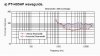
I looked up the vertical beamwidth of the PT H95HF, which is approx. 90 degrees at 1200Hz. We are using the F-95HF, which I could not find beamwidth graphs for. Zilch, do you know if they are posted anywhere?
There are no published specs for PT waveguides specifically that I'm aware of, other than in the white paper. Those shown for products incorporating them include that of the midbass driver at crossover, so they're not very informative in this specific regard. 80°, it says:

http://www.jblpro.com/ae/pdf/spec_shts/AC2212_95.pdf

Pattern control is supposedly better at the lower frequencies with the PT-H versions, but I'd guess PT-F is similar in the region of interest here:

attachment.php
 

Attachments

  • PT-H95HF Beamwidth.jpg
    PT-H95HF Beamwidth.jpg
    43 KB · Views: 699
Since this particular waveguide's vertical coverage falls, as you stated, from 90 degrees to 40~60 degrees at 2kHz, should a designer seek to restrict the pattern to 40~60 degrees at 1.2 kHz, if that's the crossover? And where to set the nulls to achieve this?

More likely, I'm assuming you want to set nulls which will tailor the vertical pattern so as to make a more gradual transition from 40 degrees to 90 degrees. So the pattern punctuation yields a smooth response and directivity overall.

The more off-axis energy there is at the null position, the deeper the null will be. In a way, that's counter-intuitive because you would expect that if the energy is low, the nulls would make it lower. But that's not the case because two sound sources are combining destructively, so the more energy that's there, the more destructive interference there will be.

That's why it's nice to have nulls set where there is at least some vertical control, and at an angle no smaller than the tweeter's vertical angle through the passband. The nulls will almost certainly cause amplitude to drop more (compared to on-axis) than the horn's angular coverage does, so you'll be able to see the nulls if the horn is providing energy there. On the other hand, if coupling isn't strong because of crossover slopes and directivity, off-axis amplitude at the null angle may not fall much below what it is an octave higher up, where the horn alone sets the pattern. That's the goal. You want as little ripple as possible.
 
Selenium D220Ti and econowaveguide measurements

Measurement without any equalization
-------------------------------------
I am using Soundeasy, Digital MLS.

I am getting inconsistently quality from the D220 drivers, one is OK the other has 2 notches of about 5dB at 3Khz and 7Khz. The starts to attentuate starting 8.5Khz, about 5db to 20Khz(this part is normal). Are the notches normal for this driver? I don't get them from B&C De250. Any comment?

The good D220 seems ok with econowaveguide, fairly flat(+/- 2db) to 7Khz and starts dropping about 5db to 20Khz. I think this normal.

I am trying to get a screen capture program so that I can display the o/p here. Any suggestion?
 
Alt + Print Screen captures the screen to your clipboard.

Paste into Paint and save as .jpg

Crop and resize in your photo editor as appropriate to upload and post....
 
bmp size too large to display

I manage to capture the screen display in bmp file 674K size, too large for display here.

Anyone suggests what compression I need to perform in order to display here?

cheers.
 
I manage to capture the screen display in bmp file 674K size, too large for display here.

Anyone suggests what compression I need to perform in order to display here?

cheers.
Max sizes are displayed in the "Manage Attachments" dialog window.
 
Back
Top Bottom