• The move to the new server is done. There are some software and database maintenance updates in process. This has us passing the hat around to help out. We appreciate any donations. Seriously, even a dollar helps. The payment page may be found here - https://www.audiokarma.org/support.html

Zilch's AK Design Collaborative - Econowave Speaker

Regarding the charts in post 4878, what changes did you make to get from the 3/2 response to the 3/11 response?

Change to 6.8 uF and 0.8 mH?
Changed R1 to 12.5 Ohms also in the high sensitivity circuit.

[Edit: Changed it back to 16 Ohms once I installed the L-pad.]

I'm not posting final values 'til it's done; not sure about it playing this low, but I've certainly filled in the hole. :dunno:

I've got to run the impedance and transfer function, and Spice it to verify.

Also need to see how it plays with a couple of woofs here.... :yes:
 
Last edited:
Speaking of taping off surfaces, I had to cut the WG cutout really close to the rim of the cab. I worked out that I could do it with a jigsaw resting on top of the rim (rather than against the baffle surface) if the saw blade was more than 3" long. I taped up the edge to prevent scraping it. It takes a steady hand but it's totally doable. Works even better if you have an assistant vacuuming off the sawdust so you can see where you're going.

picture.php


Here is the next victim prior to surgery.

I screw down a block of roughly the same height as the edge of the cabinet. This helps me keep the jigsaw level. I move it about depending on what edge I am cutting. I use two for the edge above the woofer cutout.

I wish I had an assistant to vacuum up the sawdust. My jigsaw has a laser pointer and that helped me to try to stay on the mark.

If I had a disc sander, I would use it to remove the material from the waveguide. I am very limited in the powertool department.

I'll try just removing 1/8" from each side tonight.

Thank you for your comments.
 
Nice work Wayne! Now I'm inspired. I have a pair of bullnose Advents that I originally considered installing the stock EWG in. Doesn't look like that took too much shoehorning. Perhaps the square horn won't get installed after all...
 
Last edited:
Nice work Wayne! Now I'm inspired. I have a pair of bullnose Advents that I originally considered installing the stock EWG in. Doesn't look like that took too much shoehorning. Perhaps the square horn won't get installed after all...

Thank you very much.

I think it's time for more folks to start making sawdust with their Advents.

Here is speaker #2

picture.php


I only removed 1/8" from each side of the waveguide this time. It was a mighty tight fit. I needed to use a putty knife to wedge the waveguide under the beading. I would say that 3/16" would be a good compromise.

Now it's time to re-foam the woofers.

Thanks to everyone who has contributed to this thread. Hopefully by next week I'll be joining you in listening to the Ewaves.
 
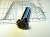
Key Seat Cutter:

There's Dremel bits like this, no?

Or that will do the same deed? :dunno:

attachment.php
 

Attachments

  • Key Set Cutter.jpg
    Key Set Cutter.jpg
    66.4 KB · Views: 216
Changed R1 to 12.5 Ohms also in the high sensitivity circuit.

I'm not posting final values 'til it's done; not sure about it playing this low, but I've certainly filled in the hole. :dunno:

I've got to run the impedance and transfer function, and Spice it to verify.

Also need to see how it plays with a couple of woofs here.... :yes:

Cool. I made a model of the LE14 crossover in 5Spice, just to see what increasing C1 would do for it. Looks like about +4.5 dB at 2K by changing to 6.8 uF. I figure that's as easy tweak when I get my DE250s if I want to try it.
 
Thank you very much.

I think it's time for more folks to start making sawdust with their Advents.

Here is speaker #2

picture.php


I only removed 1/8" from each side of the waveguide this time. It was a mighty tight fit. I needed to use a putty knife to wedge the waveguide under the beading. I would say that 3/16" would be a good compromise.

Now it's time to re-foam the woofers.

Thanks to everyone who has contributed to this thread. Hopefully by next week I'll be joining you in listening to the Ewaves.

Excellent work on those NLAs fitting those in. I have a set of NLAs myself, might give this a try.
 
Updated w/LE14A; with L-pad, R1 is back at 16 Ohms. EQ'd, this driver is 3-4 dB more sensitive than D220Ti, so use the low sensitivity highpass filter w/DE-250 & LE14A:

http://www.audiokarma.org/forums/showthread.php?p=2575679#post2575679

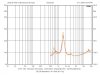
I'll try that tomorrow, and measure the voltage drive. Here's the driver/waveguide impedances:

attachment.php

WT2 says Fs = 1.582 and 1.575 kHz, respectively.... :yes:
 

Attachments

  • DE 250 Impdedance.jpg
    DE 250 Impdedance.jpg
    59.3 KB · Views: 322
Last edited:
Last edited:
Voltage Drives and Frequency Response:

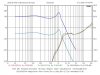
Voltage drives show what the filters are actually delivering to the driver terminals. It's the rubber hitting the road, so to speak.

Showing both versions of the E'Wave crossover with the highpass tweak described above, and confirming again the soundness of Jack's implementation of Wayne's HF comp scheme, the interaction of the L-pad and the impedance peak is apparent in a "rounding" of the highpass filter knee:

attachment.php

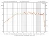
Axial frequency response of 900ss's two DE-250 drivers:

attachment.php
 

Attachments

  • DE 250 Voltage Drive.jpg
    DE 250 Voltage Drive.jpg
    71.1 KB · Views: 455
  • DE 250 FR.jpg
    DE 250 FR.jpg
    63.7 KB · Views: 281
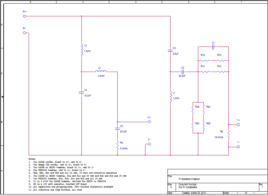
Im a little lost here or I just cant read this correctly, i was looking at the Pi 4 crossover wayne parham posted and in note 8 on the bottom it states that R3 is a 100 watt 8 ohm resistor mounted off of the board. Is that correct or should it be a 10 watt, Ive never seen a 100 watt used in crossovers before, but just because I havent seen it dont mean much because im a rookie at this stuff. Where would you even find one of these at?
 
I dont know what that resistor does. As to its high rating, it may be because Wayne designed his crossovers with possible sound reinforcement use. Like the resistors in the compensation of the high frequencies, he quadruples the resistors, (usually 10 watts each) and configures them so they equal the same ohm value as each individual resistor did, but with 4 times the wattage.

Perhaps this is why its such a high value? gonna take someone wiser than I to say for sure, but that's my guess:yes:


Lord, its been a long day, that resistor is part of the zobel, and that's why its value is so high, so that it can with stand long. hard play sessions. This sort of bullet proof building isnt really necessary for home use, unless it a really big room and you crank it to sound reinforcement levels, and I mean the levels like a loud band would play at. If that much sound is in your home, you ears will be gone and the police called! Wayne's concern are that if a lighter resistor is used and the speaker gets used in that fashion, damage can ocurr. I think I used 10 watt resistors in the compensation end of the crossover, and even at loud as hell home levels, were barely warm.
Russellc
 
Last edited:
It's the Zobel conjugate resistor, the Zobel comprising a shunt across the woofer at certain frequencies, and there's potentially high dissipation. Wayne anticipates high-power SR use of 4-Pi in this design.

Zobel low-frequency impedance compensation is optional in E'Wave, depending upon which woofers the builder uses, and how much optimization of the lowpass filter is necessary or desired.... :yes:
 
Last edited:
Back
Top Bottom