• The move to the new server is done. There are some software and database maintenance updates in process. This has us passing the hat around to help out. We appreciate any donations. Seriously, even a dollar helps. The payment page may be found here - https://www.audiokarma.org/support.html

Zilch's AK Design Collaborative - Econowave Speaker

Jack,

I hadn't thought of using the CX-3400 "split mode" either. Cool!

Very interested in what ur developing. But confused. Are you considering a single x-over frequency now, for active or passive -- and designing a new compensation scheme?

I think 2kHz looks good.:yikes:

BTW, I'm amazed that fixing tiny leaks in a ported cab make so much difference. But that's tuning, right?
 
Horn / waveguide characteristics

If directivity is constant, then the amplitude response anywhere in the pattern is the same as the plane wave tube of the compression driver. What the crossover needs to do is provide a conjugate of the driver's power response. In other words, it is providing electrical EQ for the driver.

If two horns both provide constant directivity but each has different angular coverage, then the one with smaller pattern will be louder within the pattern than the one with a larger pattern. It is focusing its energy into a smaller space. The louder one may need less power input, if you want to match volume levels with another source. However, they will both need the exact same EQ, so the compensation circuits should be the same.

The bottom line is that if you're talking about horns/waveguides with constant directivity, then the top-octave compensation circuit you'll use will be basically the same. Some may add a notch filter to tame a breakup mode peak or something, but that's specific to the compression driver, not the horn.

If you're using horns properly, above the frequency where the horn is reactive, and the horn provides constant directivity, then it shouldn't do anything to the amplitude response up to about 13kHz (for a 1" exit driver). The amplitude response tracks the power response and looks just like the driver is mounted on a plane wave tube.

A 1” exit compression driver is generally flat to 3kHz or 4kHz or so, and then falls off at 6dB/octave, except in cases where diaphragm breakup creates peaks and notches along this general trend. The conjugate filter, then, is a shelf of flat response, followed by 6dB/octave augmentation above 4kHz or so.

If a CD horn has a radiused entry like the Eminence H290 and most of the ones I've seen mentioned in this thread, then directivity will start to collapse around 13kHz or so. This is because the exit angle of the compression driver is 8-10 degrees, and that is what sets the pattern above 13kHz. It marks the end of CD bandwidth, and provides some acoustic EQ in the top octave. Horns with diffraction slots can maintain higher frequency CD, depending on the size of the slot, but they suffer from astigmatism as a result.

There are a handful of horn features that determine the way a horn behaves. This is a list of a few of them, the main ones:

1. Flare shape sets the acoustic loading as a function of frequency. Some shapes (exponential, for example) load low frequencies better than high. So they will modify the power response according to the acoustic load impedance.

2. A similar issue, reflections from abrupt transitions within the horn cause standing wave nodes to form, changing the acoustic impedance and modifying power response.

3. Acoustic filter chambers and other acoustic devices are sometimes added to modify the response. An expansion chamber in the throat forms a low-pass filter. While not usually seen in tweeters, they're common in basshorns. For that matter, rear chamber size modifies diaphragm resonance and can be set to cancel the first reactive peak of a standing wave node in a truncated horn.

Each of these will manifest themselves with changes in amplitude response compared to a plane wave tube (or CD) measurement, and they will show up off-axis as well as on-axis.

The following additional features modify horn directivity, and show up mostly as differences off-axis compared with the forward axis:

4. Phase plugs are used to reduce path length differences between the diaphragm and the throat entrance. It extends high frequency response by improving the coherency of the wavefront entering the throat. However, since its job is to match the shape of the diaphragm to the shape of the horn entrance, each horn should have its own phase plug. Since the phase plug is an integral part of the compression driver, some drivers are better suited to a particular horn than others.

5. Diffraction slots are sometimes used to make the source orifice smaller, increasing the frequency before throat beaming sets in. However, this causes off-axis astigmatism because the apparent source location is the diffraction edge. On axis, the source location is the phase plug but off-axis, it is the diffraction edge.

6. Horns with deeply curved side walls (like exponential and tractrix) have collapsing directivity throughout the passband. As frequency rises, the coverage angle narrows. This creates acoustic EQ on-axis, because as frequency rises, the sound becomes more and more focused, increasing HF amplitude on axis at the expense of reduced output off-axis.

7. Horns with straight walls have constant directivity. The wall angle sets the pattern, down to the frequency where the mouth dimensions cause it to act as a diffraction slot. The sound coming from the compression driver is roughly planar (because of the phase plug) so the throat angle is usually radiused to gradually match the flare angle or it is formed with an initial diffraction slot to widen the pattern at high frequency.

8. At low frequency, the mouth acts as a diffraction slot, widening the pattern. This is the point where the horn is said to lose pattern control. If the horn is round, it will widen at all angles at some frequency determined by its diameter. If the mouth is square, then it will lose pattern control in the vertical plane and the horizontal plane at the same frequency, but the diagonal distance is greater, so pattern control is slightly different on the diagonals. If the mouth is asymmetrical, then pattern control is lost at a higher frequency along the narrow axis before the wider one. So at low frequency, a horn with a wide mouth will lose control in the vertical before losing control in the horizontal plane.

9. Just before the pattern widens, over a narrow range of frequencies above the frequency where pattern control is lost, it narrows. So for a horn with 60 degree pattern, for example, it will narrow to 45 or 50 degrees briefly at the low end just before it widens up as it loses pattern control. Some CD horns are slightly curved or have a final flare section at a slightly greater angle. This serves to keep the pattern more constant at the low range just before the pattern widens.

10. Asymmetrical horns provide angular coverage that matches their wall angle at high frequency. At low frequency, the narrow dimension loses directivity control first. So there is a range of low frequencies where the narrow dimension has lost control and has a wide pattern. In this range, the horn is said to pattern-flip.

In any of the above mentioned cases where directivity changes becomming narrower for whatever reason, it will be accompanied by increased output on-axis and within the coverage pattern. Narrowed directivity is beaming, a focusing of the sound in a tighter pattern, so it is louder in that area at the expense of reduced sound off-axis. Likewise, any condition that causes directivity to widen spreads the sound out more, distributing the acoustic energy over a larger area, and decreasing the on-axis sound pressure level.

 
Jack,

I hadn't thought of using the CX-3400 "split mode" either. Cool!

Very interested in what ur developing. But confused. Are you considering a single x-over frequency now, for active or passive -- and designing a new compensation scheme?

I think 2kHz looks good.:yikes:

BTW, I'm amazed that fixing tiny leaks in a ported cab make so much difference. But that's tuning, right?

The passive crossover developed for the EconoWave allowed shifting the low pass and high pass frequencies to suit the drivers performance and essentially flatten their responses during the crossover region. That can't be done with zero ohm drives as used in active (bi-amp) configurations. The crossover for a bi-amped system needs to have the same frequency for both high and low pass, as I discovered. That means the large bump in response at around 1.6 KHz will need to be dealt with differently in this version. The passive crossover is about as simple as it can get, and really does a nice job. This active version will use a different HF compensation, which may not work with the passive version. At any rate it will be more complex, so the passive crossover already done will be the most desirable system to use passively.

The EconoWave as first configured, is not easily adapted to bi-amping, since the drivers performance was flattened by changing the frequencies of the crossover. This version will be for those who want to bi-amp their speakers. Adding an electronic crossover and another amplifier will increase the cost, but may be very desirable to some folks. So there will be two versions.

Yes, I was amazed as well at the small air leaks effect on performance. When the clones were operating as rear loaded horns, the cabinets were untuned, and the opening to the horn section was so large, a small leak didn't make much difference. But a small leak can effect performance in a tuned cabinet.
 
Company coming tonight, so I can't work on the Bi-Amped EconoWave till tomorrow. But while cleaning the porch, some thoughts about my previous post entered my mind. Why not use the 3 KHz hi pass and Wayne Parhams HF compensation? It does such a nice job of flattening the D220Ti's response. Adding a parallel filter circuit is not so different than adding another higher frequency passive xover. Get out of the box, Jack.

Just remove the 1.5 Mh inductor and 12 Microfarad cap, and drive the woofer straight from the bass amplifier. Connect the HF amplifier to the existing Econowave HF section. Heres an FR of what happens. Same great HF response, but a slight dip at crossover frequency. The dip happens because the signal feeding the xover is not constant, but increases due to the 1.2 KHz crossover of the CX3400. Looks like it needs a little more of that 1.6 KHz bump.

Tomorrow the high pass will be lowered to whatever it takes to flatten the overall response. Maybe it won't be possible to make it as flat as the passive version, but I wouldn't bet against it.

The component count if this works will be about the same or less, and the values of capacitance will be smaller. Let's hope it works out.
 

Attachments

  • biampecono01.jpg
    biampecono01.jpg
    74.1 KB · Views: 48
Why not use the 3 KHz hi pass and Wayne Parhams HF compensation?
Because it requires a three-way active crossover (two-ways are less expensive,) and wastes an entire section, as opposed to working out a Parham comp filter with both low- and highpass filters operating at the same frequency.

Used in the conventional manner, the three-way CX3400 could also drive a sub (or several,) as well. :yes:

[UT, oh, what have I DONE? JackLab gonna be building SUBS next.... :D ]
 
Because it requires a three-way active crossover (two-ways are less expensive,) and wastes an entire section, as opposed to working out a Parham comp filter with both low- and highpass filters operating at the same frequency.

Used in the conventional manner, the three-way CX3400 could also drive a sub (or several,) as well. :yes:

[UT, oh, what have I DONE? JackLab gonna be building SUBS next.... :D ]

The CX-3400 is still operating in a two way mode with crossover frequency set at 1.2 KHz. The 3 KHz section from the passive crossover is what allowed the reduction of the 1.6 KHz bump. It will still allow that, except now it's input signal is variable due to the 1.2 KHZ of the CX-3400, not constant. I believe enough of the 1.6 KHz bump can be used to flatten what FR was shown.

I had locked myself into the "active" xover box, and needed to adjust my options. The 3 KHz passive hi pass takes fewer parts than a parallel notch filter and HF reducing circuit. Why not use what has already been proven to work? And who says you can't use a passive xover as a compensation filter?

Nah, we don't want to start building subs. Got enough problems trying to build speakers.
 
Ahh, I see now. I was thinking you were still using the active highpass at 3 kHz.

Conceptually, if a comp filter can be designed to flatten the EconoWave response standing alone, then builders using an active crossover can dial it to whatever frequency works best with their woofer, within the usable range.

I don't believe we yet know what that range is using the typical active 24 dB/octave slope, let alone others which some users may want to use. I'm suggesting comp it using an 800 Hz or 1 kHz highpass, perhaps, for maximum versatility, and let the active user then roll it off at whatever higher frequency might be appropriate for use in their system.

http://audiokarma.org/forums/showthread.php?p=1677025#post1677025
 
Maybe the 2214H is not right for bi-amping.

I tried using the existing 3 KHz passive high pass as part of the HF correction for the bi-amped EconoWave, but came up lacking. Still had a big dip in the midst of the response, as detailed a few posts back. Thought that maybe lowering the passive HP would help solve the problem.

The first passive freq I tried was 2 KHz, with the electronic crossover still set at 1.2 KHz. Still didn't get it done. I made pics of the FR's of all the HF's, LF's, and combined. Then after looking at the FR's, I became confused. They were made with the CX-3400 set at 1.2 KHz on the front panel Frequency select knob. But looking at the FR's made on the DEQ-2496 it doesn't seem like it can be accurate. I read the manual again for CX-3400 and checked the specifications page. No mention of accuracy for the Frequency Selector knobs. HMM....

And how about accuracy of the DEQ- 2496? It has frequencies marked all along the bottom, but which of the displayed bands corresponds to the markings underneath? HMM.... And again, how accurate is it? I need to do some more reading to familiarize myself with the instrumentation I have, and what its limits and capabilities really are. No sense posting anymore FR's till I know they are truly accurate, or at least meaningful.

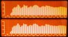
Since I was having trouble making sense of the bi-amped version, and the cabinets in use for this test will ultimately be used as passive EconoWaves using the previously developed crossover, I substituted the entire passive crossover for the bi-amped stuff. The FR's shown here says that the 2214 will certainly make a decent woofer for such use. The top FR is with the 2214H operating with no resistance across it. The bottom shows it with a 50 ohms, 40 w resistor across the woofer as JBL used it in the 4425. Not much difference at all in this configuration. These FRs are not related to absolute accuracy, and don't need to be, since the component values were calculated to set the accuracy of the crossover. The DEQ-2496 is simply checking the response to changes in frequency. It is quite good at that, even though at this point, I don't know which bar is which frequency. Maybe a detailed reading of the manual will clarify that.

Looking at the HF results, it seems that using the passive HP in the bi-amped version should work quite well, but the problem is the severe response variations of the 2214H. After I learn enough to be sure of my measurements, the rest of the details can probably be worked out.

Storm was up today, and I replaced the push pin terminals in his Altec 846B Valencia crossovers with binding posts which will accept banana plugs. He brought me a pair of Aztec speakers which are 3 ways, and a little rough, although the speakers look nice. Haven't heard them yet, but will probably make a separate post about them. I have heard of Aztec, but never heard or even seen a pair till today. Thanks, Storm. Storm gave me the Altec Santana cabinets which became my present avatar, and posted on this forum as Ocupatto.
 

Attachments

  • 2214econo.jpg
    2214econo.jpg
    81 KB · Views: 49
Those are certainly looking good, Jack!

I have found the frequency knobs on CX3400 to be close, but not precise. Verify with RTA.

On RTA page 1 and/or 2, you can dial through the bands with one of the right knobs and read the frequency and level on screen right. In average mode, the levels are stable enough to record driver response data and transcribe into filter models.

That should help you ID them.... :yes:
 
Jack, could you run a nearfield of the 2214H including port output?

Following....

Sure, be glad to. Tell me how close to the 2214H you want the microphone, since nearfield to me may mean something different than it does to you. And the port FR is with the mike right at the exit of the port?
 
Thanks Jack, that would be awesome.

When I measured my 9844s nearfield, which are vented cabs, I followed Zilch's recommendation, which was about 3 inches forward of the baffle at a point equidistant between the woofer and one port (dual ports.)

I think it would be instructive to see how your LF is working minimizing room effects.


Sure, be glad to. Tell me how close to the 2214H you want the microphone, since nearfield to me may mean something different than it does to you. And the port FR is with the mike right at the exit of the port?
 
Skywave-rider, here's your nearfield measurement

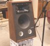
I recorded the nearfield FR as you requested, skywave-rider. Pics are included with the speaker on a milk crate showing the mic placement, and the measured FR. My mic stand wouldn't let me get the mic low enough, so had to raise the cabinet.


Those are certainly looking good, Jack!

The frequency knobs on CX3400 are close, but not precise. Verify with RTA.

On RTA page 1 and/or 2, you can dial through the bands with one of the right knobs and read the frequency and level on screen right. In average mode, the levels are stable enough to record driver response data and transcribe into filter models.

That should help you ID them.... :yes:

Zilch, I measured and took pictures of the FR's today with the 2214H on the right side running with the xover frequency set at 9 KHz, so we had a reference point. Then set the xover at 2 KHZ, took a pic, dropped a notch, took another pic, etc, til we were at 1.2 KHz. There are seven notches between 1.2 KHz and 2 KHz. After reducing the FR's, and making a panorama image, it was easy to see the changes as the crossover setting knob was reduced one click at a time. Looking at the displayed band that Behringer calls 1.25 KHz, it dropped three db at a setting three clicks below the 2 KHz front panel setting. At 2.5 KHz, it was down roughly another 18 db. That clarified that an actual xover setting of 1.2 KHz happens 5 notches above the front panel callout for 1.2 KHz.

When the front panel setting was set on 1.2 KHz, the band that is between 630 and 800 Hz was the one where the drop was 3 db, and by 1.25 Khz it was down another 18 db or so. 1.2 KHz front panel setting is actually around 700 Hz.

If we use the RTA as a standard, even though it has no accuracy specifications either, the calibration of the CX-3400 panel labeled settings is off considerably, in my eye. I can live with that, and it will be much easier now, knowing where things really stand, than when it was assumed that 1.2 KHz meant 1.2 KHz. Now maybe the finished design can be accomplished.

Hopefully the DEQ 2496 is more accurate, due to the fact it is essentially a digital processor, and crystals are pretty accurate. The CX 3400 is an analog circuit as I understand it, and it isn't going to have a lot of precision parts for it's price.

Should have done that measurement before even starting. Wasted several days of time. Oh well, I learned a lot looking back on the experience.
 

Attachments

  • nearfield01.jpg
    nearfield01.jpg
    97.3 KB · Views: 119
  • nearfield02.jpg
    nearfield02.jpg
    77.5 KB · Views: 75
When the front panel setting was set on 1.2 KHz, the band that is between 630 and 800 Hz was the one where the drop was 3 db, and by 1.25 Khz it was down another 18 db or so. 1.2 KHz front panel setting is actually around 700 Hz.
It's L/R 24 dB, so -6 dB would be definitive, not -3 dB, no?

What we're seeing on RTA is the acoustic response i.e., the driver rolloff combined with the voltage drive. The only way I have figured to precisely define the actual crossover point of a system is to measure the inverse phase notch using MLS. That's easy using CX3400 just hitting the "Inv" button on the HF driver.

The notch appears on RTA as well, but its lower resolution provides more like an "estimate."
 
I recorded the nearfield FR as you requested, skywave-rider. Pics are included with the speaker on a milk crate showing the mic placement, and the measured FR. My mic stand wouldn't let me get the mic low enough, so had to raise the cabinet.

Thanks again, Jack.

IMHO, your low end looks very nice indeed.
I presume you measured wide open, without low pass.

Re the CX3400 accuracy -- I will try to give my system a measure today to compare to your revelations.

BTW, that's a real good looking speaker.
 
It's L/R 24 dB, so -6 dB would be definitive, not -3 dB, no?

What we're seeing on RTA is the acoustic response i.e., the driver rolloff combined with the voltage drive. The only way I have figured to precisely define the actual crossover point of a system is to measure the inverse phase notch using MLS. That's easy using CX3400 just hitting the "Inv" button on the HF driver.

The notch appears on RTA as well, but its lower resolution provides more like an "estimate."

I should have re-read Dickason as well before measuring the FR's of the CX-3400. You are correct, -6 db is the definitive crossover spot for a L/R fourth order filter. But a couple places in the manual talked about crossover frequencies and adjacent bands, and led me to believe -3 db was the definition of the crossover frequency. Obviously they were talking about summing the output of adjacent channels, and not the crossover frequency. The manual doesn't define the crossover frequency level, I guess they assume we know.

Even using -6 db, the 1.2 KHz crossover is achieved at the midpoint of the 1.2 KHZ and 2 KHz front panel indications. Still a significant error. I will measure the left channel today so I know exactly where it happens on both channels, and then will attempt to put the EconoWave HF onto the the JBL 2214H's.

Thanks for catching my error. The electronic crossover needs to be set exactly for integration with the HF, but after the design of the HF compensation is done, then some variation in the settings should be tolerated.
 
Jack and Zilch,
I made some RTAs (nearfield woofer and 1 meter) of my active system [comprised of JBL Econoguide/BMS 4550/EV Sentry 8" woofer/Behringer CX3400/Trends TA10.1 HF amp/Crown PS-200LF.]
I get a -6dB notch at what "appears" to be 1.2k -- and I am using that as my x-over point.

Nearfields posted to show 3 x-over selections on the 3400. Those maybe don't look right. I think it would have been better to do that with the HF since it's more consistent in output....

My EQ on DEQ2496 was set bypassed.
attachment.php
 

Attachments

  • econo 6_30_08 post copy.jpg
    econo 6_30_08 post copy.jpg
    190.9 KB · Views: 452
Hi, Skywave!

Your results are similar to what Jack has found, BUT the system response is correct.

In Dickason, you'll see that nearfied woofer response measurements are not valid in the midrange and above, as shorter wavelength frequencies from the cone cancel each other; they're coming concentrically from 360° around the mic.

Another way to see what the crossover is doing is to look directly at the voltage drives. You can configure the RTA to do that, and it's probably safe using the CX3400 outputs as input.

If you do it with the amp outputs, however, use input isolation transformers on the RTA to avoid ground conflicts with the amps. Amp outputs should be loaded, also, with either resistive or driver loads.... :yes:
 
Hi, Skywave!

Your results are similar to what Jack has found, BUT the system response is correct.

Cool, so we're calling that fairly accurate, at least at 1.2k.

In Dickason, you'll see that nearfied woofer response measurements are not valid in the midrange and above, as shorter wavelength frequencies from the cone cancel each other; they're coming concentrically from 360° around the mic.

That makes sense, thanks, Zilch. [P.S., write the book....]

Another way to see what the crossover is doing is to look directly at the voltage drives. You can configure the RTA to do that, and it's probably safe using the CX3400 outputs as input.

So the line outs of the 3400 directly into the DEQ2496 line ins, cool, did not think of doing it. :thmbsp: Doing that with a passive crossover, use a dummy load or parallel off the driver and a 1:1 isolation transformer, and keep the volume down , I assume.:tongue: Neato:smoke:
 
Hi Skywave-rider.

You got some nice FR's. Apparently the BMS driver does a better job below 1.2 KHz than the Selenium. I think I am fighting a losing battle with the components being used. The 2214H has a dip in response which coincides with 1.2 KHz roughly. The Selenium runs out of steam at around 1.5 KHz, and doesn't respond good anywhere less than that.

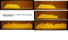
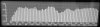
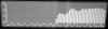
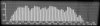
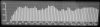
The FR's shown here are first the JBL 2214H running full range. Next is the Selenium running full range. Both of them seem dead at the crossover spot chosen. The CD compensation switch is on, so the HF output of the Selenium is a little higher and flatter, but only above 3 Khz. At the crossover frequency there is no difference to speak of.

The third FR is of the total response, with phase reversed. Note the dip at 1.25 KHz. Fourth is total response in phase. Still got a dip. Drivers just don't get it done at that frequency.

Last FR is with the crossover raised to about 2KHz+. This one is also using the CD compensation from the CX-3400. It looks like it should be easy to fix the response, but the crossover is higher than we wanted to run the EconoWave.

Zilch, maybe the response of the woofer is related to your description given to skywave-rider, and is really better than it looks. It sounds absolutely great when used with the EconoWave passive crossover. Am I doing something wrong with the D220Ti?

What now, Kemo Sabe?

Edit: What happened to my color?
 

Attachments

  • JBLFRinphase.jpg
    JBLFRinphase.jpg
    36.3 KB · Views: 24
  • JBLFRrevpol.jpg
    JBLFRrevpol.jpg
    34.1 KB · Views: 22
  • atweetfull.jpg
    atweetfull.jpg
    33.8 KB · Views: 26
  • jbl2214full.jpg
    jbl2214full.jpg
    34.2 KB · Views: 26
  • JBLSelat2KHz.jpg
    JBLSelat2KHz.jpg
    36.8 KB · Views: 28
Back
Top Bottom