• The move to the new server is done. There are some software and database maintenance updates in process. This has us passing the hat around to help out. We appreciate any donations. Seriously, even a dollar helps. The payment page may be found here - https://www.audiokarma.org/support.html

Zilch's AK Design Collaborative - Econowave Speaker

Matching directivity in the vertical and the horizontal planes

I've done a couple of little illustrations that show what the nulls look like with respect to angular coverage. A comparison is made between axisymmetrical horns and asymmetrical horns when used in DI-matched two-way speakers.

I've also included response charts made with LMS in this thread. They're in my reply to Bill Epstein (at the link below). The illustrations plot the angular coverage, and the response charts show actual amplitude response at various angles.

 
Thank you Wayne. I have been trying different spacings/x-over points in conjunction with the Linkwitz formula and recently realized I was going for too tall a vertical coverage angle. The link you provide is very helpful and gets me a bit closer to being comfortable with this concept.

I've done a couple of little illustrations that show what the nulls look like with respect to angular coverage. A comparison is made between axisymmetrical horns and asymmetrical horns when used in DI-matched two-way speakers.

I've also included response charts made with LMS in this thread. They're in my reply to Bill Epstein (at the link below). The illustrations plot the angular coverage, and the response charts show actual amplitude response at various angles.

 
Off-axis nulls

Do you have polars of the horn you guys are using? It looks large enough to provide decent vertical control down to around 2kHz or so. That should give you real smooth off-axis curves.

You've seen the four Pi response curves. Even with the relatively small H290 horn, the off-axis curves are good. At the null angles, I get a dip at around 1.3kHz. Output increases for about an octave and then settles back down to approximately equal the amplitude in the overlap band.

With your horn, I would expect the amplitude increase in the octave above crossover to be less. It should just dip at the nulls, and then stay at that amplitude on up in frequency, with only maybe a slight increase just above crossover.

Make baffle spacing so the null angles are just outside the horn's vertical pattern and you should be set.
 
Do you have polars of the horn you guys are using?
None in system that we've done ourselves, no. For the driver/waveguide itself, Geddes's measurements.

JBL butts a 12" woofer right up to it in this product crossed at 1.7 kHz. Perhaps you can "read" the polars for us?

http://www.jblpro.com/ae/pdf/spec_shts/AC2212_95.pdf

The 15" version is crossed a bit higher, at 2.2 kHz:

http://www.jblpro.com/ae/pdf/spec_shts/AC2215_95.pdf

And here are the 100° x 100° axisymmetric versions crossed at 1.3 kHz:

http://www.jblpro.com/ae/pdf/spec_shts/AC2212_00.pdf

http://www.jblpro.com/ae/pdf/spec_shts/AC2215_00.pdf

Finally, the axiasymmetric 60° x 40° at 2.1 and 2.2 kHz:

http://www.jblpro.com/ae/pdf/spec_shts/AC2212_64.pdf

http://www.jblpro.com/ae/pdf/spec_shts/AC2215_64.pdf
 
I didn't find any polars of the 90x50 horn by itself, but I did look at the polars of the loudspeakers that use it. From those charts, it looks to me like the directivity of the horn is a lot like the H290 I use. Aside from the nulls, it seems to start having vertical control around 3kHz.

Notice that the higher the crossover, the narrower the null angles are. Ones crossed over high have closely spaced nulls. Crossover lower and the null angle widens.

Also pay attention to the size and shape of the notch. It's narrow and deep, as much as 10dB and sometimes a bit more right at the frequency and angle where path length difference is exactly 1/2 wavelength, corresponding to 180 degrees phase difference. Then there is a wider region where the difference represents a phase anywhere from about 150 to 210 degrees or so. This is partial cancellation and it happens over a wider frequency range. That doesn't show as well in the JBL charts because the resolution isn't real high, but you can still see it.

Look at the speaker with the axisymmetrical horn. See how vertical off-axis output reaches the zero reference level both below crossover and also above it? Above about 3kHz, you have full output at all angles in the coverage pattern. Below about 1kHz, you also have full output. The nulls appear in the 1.5 to 2 octaves in between, marked with a 5dB to 10dB valley (or valleys) in that region. So off axis what you hear is full treble but a huge suck out in the overtone region from 1kHz-3kHz. Plenty of top-octave splash for the ceiling and floor.

Now look at the asymmetrical horn. At low frequency below crossover, you have full output. But at high frequency, the vertical pattern is more narrow. This reduces output at large vertical angles from -5dB to -10dB or more, depending on the angle. Since it's a 90x50 horn, you should expect -6dB at about 25 degrees up and 25 degrees down, and even less output at larger vertical angles.

At the null angles, there is a pretty well defined notch. In some of the JBL models, I think I would have been more careful to place the notches further outside the horn's vertical pattern; In some cases, they have nulls at 10 degrees. But it still shows how this works. Those notches can be used to punctuate the edge of pattern control. Above the crossover range, the horn does the work. If the horn is large enough, it can limit vertical off-axis output at or near the crossover point. If not, the pattern will widen briefly above the crossover point and then settle back down to a narrow angle just above that, where the horn is able to provide directional control.

If we place that null notch just outside the pattern, and if the horn has directional control down to the crossover frequency, you'll have a straight line of vertical coverage. Usually this ideal isn't realized, and you have about an octave above the crossover where output is higher at the edge, followed by the horn gaining control and bringing the output back down again up through the rest of the audio band. But except for the bump between 2kHz and 3kHz, output is fairly flat from the crossover point up.

Have any of you tried using the four Pi crossover? You might try breadboarding one and trying it on your speakers. I think it will work very nicely with a speaker having the horn and woofer flush mounted on the baffle. From what I can tell from the photos posted here, I think you should get pretty similar response to the four Pi with it.

I use the Eminence PSD2002 and B&C DE250 drivers. The B&C DE250 is a little bit higher sensitivity, so R1 and R2 changes are needed. It's easy to set the crossover for use with just about any compression driver by changing those two resistor values. I've worked out a chart that helps select the right values.

 
Wayne,
In our implementation, the approx. 1.6kHz x-over point suggests that if we use a 50 degree null angle there will be a widening of the vertical beamwidth as frequencies rise up until approximately 3kHz, where the waveguide gains control, as you state.

Is it better to in this case provide driver spacing which will give a wider null angle approximating the beamwidth at crossover (80 degrees roughly -- if we can rely on the JBL graph with both drivers) because that would yield more even power response?

If I understand what you’ve said previously, this may not work well with a smallish horn as used here because the nulls are less effective where energy is less concentrated. So I’m presuming that where the horn is pooping out on control, there are weaker nulls, less destructive interference.

Also, If I am reading you correctly, in practical designs, vertical beamwidth commonly broadens above crossover until the waveguide can gain control, and that is the compromise in using a more compact horn; and an advantage of your larger wooden horn.

Lastly, I have been experimenting with 1.2kHz on the Econowaveguide in an active setup, but thinking about implementing this passively. From the standpoint of vertical control, would you say this is just too low for this horn?

Thanks!
 
My four Pi crossover is 1.6kHz too. The woofer is actually using a 1.3kHz crossover, but even with this difference and third-order slopes, there's still some overlap. I always consider the two drivers to both be online between 1kHz and 2kHz.

As you are seeing by now, you can set the null angles with crossover frequency and driver position. The nulls are separated wider by using a lower crossover point or by moving the two sound sources closer together.

You have some wiggle room in the null angles because of what they are. They're not a fixed wall, but more like a fuzzy angular region of reduced amplitude. At certain precise angles and frequencies, there will be a pretty deep notch but move a tiny bit either in angle or frequency and the amplitude changes. If you were to look at them with 1/3rd octave smoothing or even 1/6th octave smoothing, what you see are valleys like my illustrations show.

Beyond the nulls, there are lobes. You can see them in the polars. So you definitely would prefer that the horn not put a lot of energy at the angles where the lobes are. This is the key to getting uniformity in the vertical plane.

The ideal horn would be one that had good vertical control down to the crossover frequency, and was small enough to allow close spacing. That would give you a lot of choices where to set the nulls.

In the real world, the smaller the horn, the less vertical control it has. Small drivers and horns allow close spacing providing wide null angles, but they also tend to have poor vertical control at low frequency. The more energy off-axis in the vertical there is, the more pronounced the nulls are and the larger the lobes outside the nulls are too. That's the tradeoff, and you have to strike a balance.

I think if you can get the nulls at 20-30 degrees with a horn having approximately 40-50 degrees pattern, that's a pretty good way to go. The lower the frequency the horn has pattern control, the better, because it will have less lobing outside the nulls.
 
These are definitely keepers.

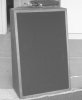
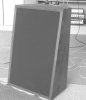
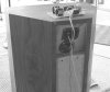
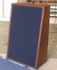
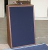
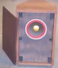
I finally got a guide made to route out the depth of the waveguides, so I could use the previously made grilles, although they required some modification. The woofers used previously were mounted on the back of the baffle, so the baffle cutout for them was smaller. Mounting the 2214H's on the front of the baffle made it necessary to widen the cutout slightly. The tuning ports were below the woofers, which meant lowering the cutouts so the ports wouldn't be blocked. And obviously, insetting the waveguides 1/4 inch, to clear the grilles, which would save cutting another 3/8 inch from the top of the grilles. The additional inset also moved the time delay a little closer to zero. Four magnets were epoxied into the grilles to correspond to the upper and lower baffle mounting screws. That makes them much easier to remove than the velcro used previously.

Here are pictures of the finished baffles and grilles of the new pair of keepers. I had black and JBL blue grille cloth. Guess which color got used? I plan to mount the crossovers on the back of the cabinets, where the patch covering the old rear loaded horn exit was. That way, they can be used with the crossovers pigtails to be driven passively, or by removing the pigtails, they can be bi-amplified. When I get Zilch his pair, we can compare results in similar cabinets, which may be a good thing.
 

Attachments

  • leftkeeper.jpg
    leftkeeper.jpg
    34 KB · Views: 93
  • rightkeeper.jpg
    rightkeeper.jpg
    43.1 KB · Views: 105
  • sunktweeter.jpg
    sunktweeter.jpg
    35.8 KB · Views: 493
  • keeperback.jpg
    keeperback.jpg
    41.3 KB · Views: 148
OMG, Jack, they are BEAUTIFUL!


Looks like JBL Blue on MY monitor screen.... :thmbsp:

Thanks, Zilch. Yes, it is JBL blue, but I can't get my computer to do color anymore on pix posted from Irfanview. And I can't seem to find how to restore it's original settings. Need to call in the Geek Squad, maybe.

OK, now color is there through another program. Still hard to tell that it's JBL blue.
 

Attachments

  • rightkeeper3.JPG
    rightkeeper3.JPG
    55.2 KB · Views: 106
  • leftkeeper3.JPG
    leftkeeper3.JPG
    34.6 KB · Views: 95
I finally got a guide made to route out the depth of the waveguides, so I could use the previously made grilles, although they required some modification. The woofers used previously were mounted on the back of the baffle, so the baffle cutout for them was smaller. Mounting the 2214H's on the front of the baffle made it necessary to widen the cutout slightly. The tuning ports were below the woofers, which meant lowering the cutouts so the ports wouldn't be blocked. And obviously, insetting the waveguides 1/4 inch, to clear the grilles, which would save cutting another 3/8 inch from the top of the grilles. The additional inset also moved the time delay a little closer to zero. Four magnets were epoxied into the grilles to correspond to the upper and lower baffle mounting screws. That makes them much easier to remove than the velcro used previously.

Here are pictures of the finished baffles and grilles of the new pair of keepers. I had black and JBL blue grille cloth. Guess which color got used? I plan to mount the crossovers on the back of the cabinets, where the patch covering the old rear loaded horn exit was. That way, they can be used with the crossovers pigtails to be driven passively, or by removing the pigtails, they can be bi-amplified. When I get Zilch his pair, we can compare results in similar cabinets, which may be a good thing.
Jackgiff:
What did you use for a circuit board there...is that a commercially available board like parts express, or of your own making? I need to clean up my crossovers! Very nice to be certain!:thmbsp:

Russellc
 
Jackgiff:
What did you use for a circuit board there...is that a commercially available board like parts express, or of your own making? I need to clean up my crossovers! Very nice to be certain!:thmbsp:

Russellc

Hi Russell, the crossover pc boards were exposed, etched, and drilled by me. I layed out an artwork sometime ago for another speaker project, and just used it for this project, with the extra resistors and capacitors hung on as best they can fit.

The pre-sensitized pc boards are available from Parts Express, but their etchant leaves a lot to be desired. I buy ferric chloride from Capitol Electronics in Phoenix. It is made by GC Electronics, and works best for me. Plus used ferric chloride is the only weedkiller I have found that will kill the razor grass that grows where it can't be chopped out by the roots. Must be the disolved copper. Good stuff.
 

Attachments

  • econowavecrossover.jpg
    econowavecrossover.jpg
    48.8 KB · Views: 128
Very nice boards indeed. Very, very nice set of econowaves. I'll have to look into board etching. Thanks for the info on the etching supplies.

Russellc
 
Dang Jack, those are beautiful. I have never made a circuit board. I will have to check on details as my crossovers look like hell compared to that.. all point wired...

Has anyone built a pair in Michigan or Ohio? I'd love to get a listen before embarking on another speaker project...
 
Almost ready for prime time.

I finished the crossovers this morning, and installed them on the New EconoWaves. They are now operating passively crossed, but it is simple to remove the crossovers and go back to bi-amped.

The first pic is the FR of one crossover running at 1.2 KHz, normal phase on top, reverse phase on bottom. The bump at around 2 KHz says the woofer still might be crossed too high. Just as the JBL LE14A likes 900 Hz better, so does the JBL 2214H.

The next two pics are the FR's of the left and right speakers crossed at 900 Hz, measured with the microphone looking right down the center of the waveguide. Moving the mike down somewhat gives a slightly improved picture, but to stay consistent, those pics weren't used.

The two 100 ohm resistors are mounted on the crossover, so that should the crossover be removed for bi-amping, the resistors go away also. They really seem to have tamed the response of the 2214H, if you compare some of the earlier FR's, when they were not there.

The crossovers will be mounted in an enclosure on the back of the cabinets, with it's pigtails being connected to the woofer and tweeter connectors. Then they will go back into the upstairs are where they can be A/B'ed with my computer speakers and the DIY 4430's of two years ago.
 

Attachments

  • NewEconoat1.2KHz.jpg
    NewEconoat1.2KHz.jpg
    54.8 KB · Views: 58
  • newconoleft.jpg
    newconoleft.jpg
    26.3 KB · Views: 57
  • newconoright.jpg
    newconoright.jpg
    29 KB · Views: 50
Congrats Jack. The woofer looks much flatter.

With those cabs especially, wouldn't you think measuring measuring mid between waveguide and woofer to be a good position anyway?

Question: you haven't done away with the variable L-pad have u?

And, how much to make me a pair?....LOL.
:tresbon:
 
Congrats Jack. The woofer looks much

flatter.

With those cabs especially, wouldn't you think measuring measuring mid between waveguide and woofer to be a good position anyway?

Question: you haven't done away with the variable L-pad have u?

And, how much to make me a pair?....LOL.
:tresbon:

All of the FR measurements that I have made have been looking right down the center of the tweeter. Zilch says that D'Appolito recommends this when taking FR measurements. The center of the drivers may well be the best approach, but to stay consistent, I will continue to measure this way.

No, the L-pad is still part of the crossover package. It is maxed out on this configuration, but it will stay in case another pair of 12 inch woofers shows up that need testing.

As far as making another pair of these, no thanks. I appreciate the compliment, but... "been there, done that." I wasted a few sides and other parts getting all the angles figured out, especially how to cut and mount the internal baffles, which were cut out of this pair with my sawzall. Seems like a waste now. Building the two pair was a labor of love, and very enjoyable, but enough is enough.

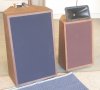
Here is my next EconoWave project, a pair of same size Baronet clones, which were built before the larger ones. I also built two pairs of these, but have given away the other pair. A pair of 10 inch Goldwood woofers were just ordered for this project. Enough of this JBL woofer stuff. Let's get into the modern world.

They presently contain a pair of Trusonic 80FR's, and while it may complicate making the grilles, the 10 inch woofer and waveguide should fit. Haven't measured the internal volume yet, but it should be around 1.5 cubic feet. This may be a bigger project than the larger size clones.
 

Attachments

  • nextecono3.jpg
    nextecono3.jpg
    42.2 KB · Views: 260
  • nextecono1.jpg
    nextecono1.jpg
    46.9 KB · Views: 75
  • nextecono2.jpg
    nextecono2.jpg
    51.3 KB · Views: 83
Back
Top Bottom