• The move to the new server is done. There are some software and database maintenance updates in process. This has us passing the hat around to help out. We appreciate any donations. Seriously, even a dollar helps. The payment page may be found here - https://www.audiokarma.org/support.html

Zilch's AK Design Collaborative - Econowave Speaker

Yes, "J" means 16 Ohms in JBL code. See the system impedance curve here:

http://www.jblpro.com/catalog/support/getfile.aspx?doctype=3&docid=1078

Yup. At the very least I'll have to halve the LP choke values and double the cap values to achieve the same crossover values for an 8 Ohm woofer and that will still only be an approximation for any randomly chosen woofer.
It's interesting that there's a huge peak in the impedance curve at around 3500 - 5000 hz. I'm looking forward to seeing what that looks like on the RTA because a voltage amplifier can't deliver much power at all into a high impedance.
I may open up these Control 1 monitors and see if I can graft the 2414H/waveguide rig onto them for grins.
After the Labor Day beers wear off. Or now...
 
So they have to be new? Why not a pair of used JBL LE-14A's?

Why not LE-14A's? Well, I'm not likely to find a set for cheap around here. The pairs I see up for auction are going for as much as the new drivers I listed or more, mostly need refoaming, and I'd have to trust that there are no other issues with the used drivers.

I know this is hallowed ground around here, but I'm not feeling huge love for the LE14A's. I thought the use of LE-14A's in a number of these systems was more due to current owners putting them to best use than it was the perfect match of the driver to the Econowave high end.

My biggest issues with the LE-14's as drivers are the glitches in the impedance curve and the rising FR at just over 1kHz that indicate to me that they'd really rather be crossed over lower. I'd rather avoid that behavior from the start than try to deal with it in the crossover. Otherwise they are decently but not spectacularly efficient (~91 dB, right?), and don't necessarily play much deeper or louder than what I've been looking at. The major advantage to me seems to be the fun of having a huge woofer in a little box.

If, as Zilch suggests, I accept that a sub will be needed, then the WN12S looks like a winner, with high sensitivity, low L, minimal peaking (for a 12" woof) between 2800 & 3500 and a nice roll off beyond. It should be an easy fit in the PE cabinets, too, and I don't think I could get Baltic Birch ply cheap enough to beat the price of those.

This isn't to say the LE14 is a bad driver, it's just that there are modern alternatives that might offer some advantage. Like the JBL PT waveguides apparently do over the 'classic' horns. Plus, there's the fun of trying something new!

Bill
 
...

This isn't to say the LE14 is a bad driver, it's just that there are modern alternatives that might offer some advantage. Like the JBL PT waveguides apparently do over the 'classic' horns. Plus, there's the fun of trying something new!

Bill

I always look at the LE-14s on ebaY, but can't quite see the deals others do.
If you find a current production woofer that works, great, and you'd be broadening our base of known compatibles.
 
It's interesting that there's a huge peak in the impedance curve at around 3500 - 5000 hz. I'm looking forward to seeing what that looks like on the RTA because a voltage amplifier can't deliver much power at all into a high impedance.
It's the 59 Ohms in the tank filter doing that. Tubes'd want some resistance in parallel with the highpass.

It looks weird in SPICE; I'm gonna have to build up that crossover and measure.

[You go first, tho.... ;) ]

My biggest issues with the LE-14's as drivers are the glitches in the impedance curve and the rising FR at just over 1kHz that indicate to me that they'd really rather be crossed over lower. I'd rather avoid that behavior from the start than try to deal with it in the crossover. Otherwise they are decently but not spectacularly efficient (~91 dB, right?), and don't necessarily play much deeper or louder than what I've been looking at. The major advantage to me seems to be the fun of having a huge woofer in a little box.
Closest we have to an EDS from JBL is the ferrite version:

http://www.audioheritage.org/vbulletin/showthread.php?t=10664

The big plus is they reach low in small boxes for classic JBL extended bass. H-1 and H-3 are the higher power versions.

I always look at the LE-14s on ebaY, but can't quite see the deals others do.
Another AKer just scored a pair of S99s for $100:

http://www.audiokarma.org/forums/showthread.php?t=250359

If you find a current production woofer that works, great, and you'd be broadening our base of known compatibles.
I agree. It'd be good to see more high-efficiency implementations.... :thmbsp:
 
Last edited:
It's the 59 Ohms in the tank filter doing that. Tubes'd want some resistance in parallel with the highpass.

It looks weird in SPICE; I'm gonna have to build up that crossover and measure.

[You go first, tho.... ;) ]

I think the tank circuit is about an octave above that. It's a strange crossover.
My RTA/Mic setup has too poor resolution to really see what's happening and I don't have other options easily available. If you feel like giving this setup a run through your rig I can ship the drivers, waveguides and crossovers for evaluation.
My D220Tis/PH612 are out on loan but I can go back to the DE10/ME10 combo for now.
The 2414H and 6" JBL Wg sounds really nice with the AC16 crossover. I'm crossing the LP over to the Altec Bolero 406Z with a separate amp and Rane AC22 set at about 2500 hz. It's very listenable and the dispersion seems very good. Lots of air and space, although the central image seems weaker than with other setups. This might be due to the 250 square feet of glass behind the speakers.

I really want to hear this HF setup with the Kef B110. I wish they'd fit in my AR3/5A Frankenspeakers with the AR woofers and B110s, but there just isn't room without major carpentry. I may try a 2-way with the B110 in a 10L ported cabinet if I find appropriate boxes.
 
My biggest issues with the LE-14's as drivers are the glitches in the impedance curve and the rising FR at just over 1kHz that indicate to me that they'd really rather be crossed over lower. I'd rather avoid that behavior from the start than try to deal with it in the crossover.


Its already been dealt with in the crossover, perhaps the only driver here that has been worked out LP crossover wise. 900hz I believe. The "rise" was discussed and dealt with.

russellc
 
My RTA/Mic setup has too poor resolution to really see what's happening and I don't have other options easily available. If you feel like giving this setup a run through your rig I can ship the drivers, waveguides and crossovers for evaluation.
Your RTA is certainly good enough to show the overall response.

No need to send anything; I have all the stuff here. If I recall my first look, the eWave filter plus a notch worked fine, but I'm curious about the factory filter now, since I'm cloning AC16 in PE cabs.

[Yeah, have the woofers, too.... ;) ]
 
Last edited:
Can I please get some feedback on what I'm doing? I'm new to this and not very knowledgeable of it and I know it's a hack job. Any questions or comments would help me understand better what I'm working with.
 
Can I please get some feedback on what I'm doing? I'm new to this and not very knowledgeable of it and I know it's a hack job. Any questions or comments would help me understand better what I'm working with.
Yes.

Though many of the same principles apply, what you are doing is off-topic in this thread, basically, and that's why it is not garnering attention. Start a thread of your own regarding your project, and members will likely be interested in discussing it. Provide links to the specs on those horns and the drivers that are mated with them there so readers don't have to research them.... :thmbsp:
 
Yes.

Though many of the same principles apply, what you are doing is off-topic in this thread, basically, and that's why it is not garnering attention. Start a thread of your own regarding your project, and members will likely be interested in discussing it. Provide links to the specs on those horns and the drivers that are mated with them there so readers don't have to research them.... :thmbsp:

My intuition had suggested that to me too. But I decided to post here as a few months ago I started a "very horny" thread and you referred me to here.

Anyhow I do see at this point there are significant differences between my dabbling and the much more scientific ideas being discussed here. I agree - an independent thread would be appropriate for my "now where do I start with this". Maybe see you over there.
 
Your RTA is certainly good enough to show the overall response.

No need to send anything; I have all the stuff here. If I recall my first look, the eWave filter plus a notch worked fine, but I'm curious about the factory filter now, since I'm cloning AC16 in PE cabs.

[Yeah, have the woofers, too.... ;) ]

I've been disappointed that additions of EQ or significant changes to the woofer crossover point (through the Rane AC22 line level xovr) register barely if at all on the RTA but I can clearly hear the effect. This leads me to believe that other effects, features, changes, etc. that the ear can pick up will not show on the RTA. I'm the guy with 6 O-scopes and a distortion analyzer just for repairing lo-fi '60s tube console amps, so I like lotsa data on what I'm tinkering with.

Overall balance is easy to see, and I can set the relative levels of woofer and tweeter amps visually with the RTA and have the levels work fine audibly.

maybe I'm worrying too much about resolution but I'd rather have too much data than too little.

****
Edit
****

Do you recall the details of the notch you used?
 
Last edited:
Do you recall the details of the notch you used?
No, but it may be in my notes. No matter, I'm about to take another run at it.

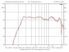
Here's the results with the factory filter:

attachment.php


attachment.php

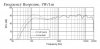
Compare to their spec:

attachment.php

Can we beat it? ;)
 

Attachments

  • AC16 HP Filter.jpg
    AC16 HP Filter.jpg
    77.4 KB · Views: 239
  • PT-B99HF 2414H AC16.jpg
    PT-B99HF 2414H AC16.jpg
    52.1 KB · Views: 238
  • AC16 FR Spec.JPG
    AC16 FR Spec.JPG
    44.7 KB · Views: 237
Last edited:
no, but it may be in my notes. No matter, i'm about to take another run at it.

Here's the results with the factory filter:

attachment.php


attachment.php

compare to their spec:

attachment.php

can we beat it? ;)

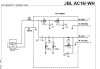
fyi

attachment.php


Note that when you follow the hookup conventions shown for the tweeter, you're connecting the lead on the schematic marked '+' to the terminal on the 2414H marked '-'. Since I'm not using a JBL woofer I reversed the polarity to the woofer. They appear to be in phase at the crossover point so I guess this was right.
 

Attachments

  • JBL AC16 CROSSOVER SCHEM.jpg
    JBL AC16 CROSSOVER SCHEM.jpg
    76.5 KB · Views: 222
Last edited:
FR looks good

When I measure this I get a moderate rolloff above 8K that looks about 6 - 8 db down at 18K. Every tweeter I measure looks this way, so it's likely an artifact of the Behringer mic. I need to find out how to load a mic EQ curve into the DEQ2496. The mic box has two different curves on it, one labeled Transfer Function and one labeled Response. They have completely different shapes, but the Frequency Response one does show a top end rolloff.
 
Impedance of JBL 2414H and waveguide without crossover

as measured here.

I was looking at this to determine if adding an Lpad to adjust HF level for use with less sensitive woofers would cause a problem. There's no significant impedance change within the passband, so a resistive attenuator should not affect the response.
My only concern is that the impedance peak is near the crossover frequency. Putting a resistive element in parallel with the driver would reduce the magnitude of the peak. This could reduce the voltage drive available at the crossover point to the driver by presenting a heavier 'load' to the series capacitors. Theoretically, this could cause loss of energy in the crossover region disproportionately when the lpad is turned down.
That's off the top of my head...

*** edit ***

That high impedance peak at the crossover point may be why the HP input cap is a small .68uf value (the ewave HP has a 4.7uf input cap). It might be possible to work out the Lpad resistive values, see how they affect the impedance at the crossover region and increase the value of the .68uf cap to match the new impedance. Tha tshould get the response back on target. I don't know if other component values would have to be changed.
attachment.php
 

Attachments

  • JBL 2414H IMPEDANCE.jpg
    JBL 2414H IMPEDANCE.jpg
    56.9 KB · Views: 213
Last edited:
Notch filter in JBL AC16 crossover to 2414H

I measured the notch filter in the crossover. They're going after something at 11khz pretty aggressively. This is a series filter. It's .06mh/59 ohms/4.2uf.

attachment.php
 

Attachments

  • JBL AC16 NOTCH FILTER.jpg
    JBL AC16 NOTCH FILTER.jpg
    132.4 KB · Views: 280
PE Trapezoid kit with DE250 and QSX waveguide

In discussions with Zilch via PM's, it was obvious that the next step up from the basic EconoWave was going to be with a better HF driver, and the B & C DE250-8 seemed to be drawing most of the attention. Also much discussion was being spent on which woofer would work well with an EconoWave approach. The apparent winner seemed to be the Dayton 12 inch Classic, model number DC-300-8. Then came the announcement of the QSC waveguide, which was a bolt on device, while the standard E"wave waveguides are screw on. The QSC is physically larger, but opens up lots of possibilities being a bolt on. Finally Parts Express offered an affordable cabinet kit which seemed ideal for building a complete system. Wow, the die was cast.

I ordered a set of cabinets, waveguides and both DE250's and DC300's to build a complete set of speakers. The original EconoWave was just the Hi end. This will be a new approach to build the entire speaker, not just a sub system. And what works here will be easily adapted to the older original EconoWave, if you don't want to spend near 3 to 4 times the price for HF drivers.

The cabinet was spec'ed as being 2 cubic feet internal volume, but built as supplied is actually 1.6 cubic feet. That is OK, as lot's of nice woofers will work in that volume, including the DC300 chosen. I opted to move the baffle out 3/4 inch to raise volume to 1.72 cubic feet. The difference in performance is not that big, but internal volume is more important to me than having 1 1/8 inch behind the baffle, which is doing nothing. The build can be done either way.

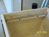
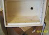
Pic's are shown detailing how I moved the baffle out. The upper and lower panel mounting blocks were installed as per stock. Then two spacers were cut from 3/4 fiber board which are one inch high. This allows the side blocking parts to fill the entire 22.75 inch height, instead of leaving large gaps in the corners as built stock. The side blocking strips are aligned with the spacers, and mounted as per instructions in the kit.

This left a gap along each side of the baffle of roughly 1/8 inch inch, which can be filled with virtually anything. I cut strips of fiber board the proper width, and glued them to the baffle edges. Before receiving the waveguides, I figured the 12 inch woofers would be front panel mounted, and the baffle glued into the cabinet. But the physical size of the waveguide is 10 inches high, and the space between the top of the woofer cutout and the cabinet top is exactly 10 inches. That simply means the woofer will be back ,mounted (which will probably be best for time alignment), and the baffle mounted to the cabinet. Then the waveguide will be screwed to the baffle. Not the way I would have designed it, but perfectly functional, and once the recipe is written, users building their own should have no problems.

Since my original thought was front mounted woofers, I routed out an area about the proper width for the DC 300, and it was roughly .15 inches deep. Whooops!! Now it will need to be filled, since the woofers will be rear mounted. Another lesson learned. Don't rush! Measure twice, cut once! ETC.

Drivers will be here in about another two or three days, which will give me time to fill my mistake. I plan to veneer the baffle front anyway, so the fill will not show. In the last two pics, wax paper shows around the edges of the baffle, which is to keep the glue from the spacers joints from sticking the baffle into the cabinet.

 

Attachments

  • Cabpan Extend.jpg
    Cabpan Extend.jpg
    66.7 KB · Views: 112
  • CabPanSideExt.jpg
    CabPanSideExt.jpg
    72.5 KB · Views: 121
  • CabPanglued.jpg
    CabPanglued.jpg
    81.7 KB · Views: 91
  • CabPanBaffWave.jpg
    CabPanBaffWave.jpg
    73.9 KB · Views: 99
Dang Jack, good work. I think that cab has great potential. Can't you flip the motor board over so the routered lip is on the inside?
 
Back
Top Bottom