• The move to the new server is done. There are some software and database maintenance updates in process. This has us passing the hat around to help out. We appreciate any donations. Seriously, even a dollar helps. The payment page may be found here - https://www.audiokarma.org/support.html

Zilch's AK Design Collaborative - Econowave Speaker

In discussions with Zilch via PM's, it was obvious that the next step up from the basic EconoWave was going to be with a better HF driver, and the B & C DE250-8 seemed to be drawing most of the attention. Also much discussion was being spent on which woofer would work well with an EconoWave approach. The apparent winner seemed to be the Dayton 12 inch Classic, model number DC-300-8. Then came the announcement of the QSC waveguide, which was a bolt on device, while the standard E"wave waveguides are screw on. The QSC is physically larger, but opens up lots of possibilities being a bolt on. Finally Parts Express offered an affordable cabinet kit which seemed ideal for building a complete system. Wow, the die was cast.

I ordered a set of cabinets, waveguides and both DE250's and DC300's to build a complete set of speakers. The original EconoWave was just the Hi end. This will be a new approach to build the entire speaker, not just a sub system. And what works here will be easily adapted to the older original EconoWave, if you don't want to spend near 3 to 4 times the price for HF drivers.

The cabinet was spec'ed as being 2 cubic feet internal volume, but built as supplied is actually 1.6 cubic feet. That is OK, as lot's of nice woofers will work in that volume, including the DC300 chosen. I opted to move the baffle out 3/4 inch to raise volume to 1.72 cubic feet. The difference in performance is not that big, but internal volume is more important to me than having 1 1/8 inch behind the baffle, which is doing nothing. The build can be done either way.

Pic's are shown detailing how I moved the baffle out. The upper and lower panel mounting blocks were installed as per stock. Then two spacers were cut from 3/4 fiber board which are one inch high. This allows the side blocking parts to fill the entire 22.75 inch height, instead of leaving large gaps in the corners as built stock. The side blocking strips are aligned with the spacers, and mounted as per instructions in the kit.

This left a gap along each side of the baffle of roughly 1/8 inch inch, which can be filled with virtually anything. I cut strips of fiber board the proper width, and glued them to the baffle edges. Before receiving the waveguides, I figured the 12 inch woofers would be front panel mounted, and the baffle glued into the cabinet. But the physical size of the waveguide is 10 inches high, and the space between the top of the woofer cutout and the cabinet top is exactly 10 inches. That simply means the woofer will be back ,mounted (which will probably be best for time alignment), and the baffle mounted to the cabinet. Then the waveguide will be screwed to the baffle. Not the way I would have designed it, but perfectly functional, and once the recipe is written, users building their own should have no problems.

Since my original thought was front mounted woofers, I routed out an area about the proper width for the DC 300, and it was roughly .15 inches deep. Whooops!! Now it will need to be filled, since the woofers will be rear mounted. Another lesson learned. Don't rush! Measure twice, cut once! ETC.

Drivers will be here in about another two or three days, which will give me time to fill my mistake. I plan to veneer the baffle front anyway, so the fill will not show. In the last two pics, wax paper shows around the edges of the baffle, which is to keep the glue from the spacers joints from sticking the baffle into the cabinet.

hey Jack,

I'm a little confused. I've been following the "No quarter" project of Augerpro's over on AVS and HT guide. Info is in threads entitled "whats Brandon cooking" where he is doing something similar, with the QSC waveguide. They are having a problem over there that is phase related, apparently there is such a difference they may only be able to cure it actively, but several ideas have been put forth to address the problem.

I suppose they are talking about the physical mis match between the driver and the woofer's accoustic centers.......but if this is the case, why isnt it a problem with Wayne's 4PI, whose H290 horn is even longer than the QSC.
Did Econowave address the phase problem somehow, or is E'wave's JBL guide
being quite a bit shorter not a problem? Or is this phase issue caused by other factors?

Just wondering...and thanks for playing with the QSC/DE 250 combo....there seems to be so much potential there, something just isnt right yet, maybe a bit bright, I have the < 95 db crossover with 2235H, and the recommended
16 ohm resistors in R1 and R2 positions, but still have the L-pad at 9:00.


Russellc
 
Thanks, Jack.
Is there a reason you did not go flush with the baffle?

Going the extra 3/8 inch offers such a small gain in internal volume, it didn't seem worth it at the time. However, the possibility of doing that still remains, and may be used if the time displacement issues seem to warrant it. Also building a new baffle and putting it on the cabinet front is another possibility. But using the cabinet as is seemed better than involving new users in a woodworking project. The fix as described is pretty straightforward, as well as unnecessary. The cabinet will work just fine built as supplied.

Dang Jack, good work. I think that cab has great potential. Can't you flip the motor board over so the routered lip is on the inside?

Flipping it over would reverse the angle of the edges, and make adding a spacer more difficult. That could certainly be done, but the router filling won't be a problem, and won't involve any table saw work.

hey Jack,

I'm a little confused. I've been following the "No quarter" project of Augerpro's over on AVS and HT guide. Info is in threads entitled "whats Brandon cooking" where he is doing something similar, with the QSC waveguide. They are having a problem over there that is phase related, apparently there is such a difference they may only be able to cure it actively, but several ideas have been put forth to address the problem.

I suppose they are talking about the physical mis match between the driver and the woofer's accoustic centers.......but if this is the case, why isnt it a problem with Wayne's 4PI, whose H290 horn is even longer than the QSC.
Did Econowave address the phase problem somehow, or is E'wave's JBL guide
being quite a bit shorter not a problem? Or is this phase issue caused by other factors?

Just wondering...and thanks for playing with the QSC/DE 250 combo....there seems to be so much potential there, something just isnt right yet, maybe a bit bright, I have the < 95 db crossover with 2235H, and the recommended
16 ohm resistors in R1 and R2 positions, but still have the L-pad at 9:00.


Russellc

I have not read Augerpro's stuff, so can't comment. Time delay differences are probably not a really big issue, unless you make them one. How many speakers that people really love are out there which are not "time aligned?"

There was no attention paid to "properly" time aligning the EconoWave, since no one woofer and cabinet was chosen. The phase of the drivers as shown in the crossover schematics put the phase relationship very close, but certainly not exact. Some builders played with moving their waveguide back and forth. Most didn't. And ALL are happy with their speakers.

Time alignment issues will be examined in this project, and may or may not be solved. Only time will tell.
 
And ALL are happy with their speakers.

I sure am. Despite trying other drivers and so on, The basic E'wave really delivers for the small investment.

Time alignment issues will be examined in this project, and may or may not be solved. Only time will tell.

Is there a way to measure this phase difference that is practical for the DIY
type project. like an impluse response or something? Or is it just a matter of aligning the accoustic centers of the driver?

Thanks for any clearing up of these issues for me:yes:

Russellc
 
"They are having a problem over there that is phase related, apparently there is such a difference they may only be able to cure it actively, but several ideas have been put forth to address the problem."

I took a look at the measurements posted and it seems they may be confusing Excess phase from the measurement with the actual minimum phase of the drivers. What's posted is the phase response of the driver and the from the measurement together. You need to look at what the driver is doing and ignore the phase anomalies added by the measurement.

Rob:)
 
"They are having a problem over there that is phase related, apparently there is such a difference they may only be able to cure it actively, but several ideas have been put forth to address the problem."

I took a look at the measurements posted and it seems they may be confusing Excess phase from the measurement with the actual minimum phase of the drivers. What's posted is the phase response of the driver and the from the measurement together. You need to look at what the driver is doing and ignore the phase anomalies added by the measurement.

Rob:)

Any advice for someone new to measurement as how to measure/observe what the driver is doing? (Phase wise, that is...)

Thanks for the response,
Russellc
 
Going the extra 3/8 inch offers such a small gain in internal volume, it didn't seem worth it at the time. However, the possibility of doing that still remains, and may be used if the time displacement issues seem to warrant it. Also building a new baffle and putting it on the cabinet front is another possibility. But using the cabinet as is seemed better than involving new users in a woodworking project. The fix as described is pretty straightforward, as well as unnecessary. The cabinet will work just fine built as supplied.

Jack,
I will be delving into mine fairly soon, but I would like to eliminate the edge surrounding the baffle created by the overlap of the top, bottom and side panels. I think the best way to do that would be to make the appropriate spacer, as you have, but of the required height, and place a new baffle (original one won't work I guess) flat on top of the cabinet sides and top and bottom. I would seal with a gasket and make it removable. But that can't be done if the top, bottom and sides are not pre-cut from PE to be the correct angle to meet a flat baffle. Can you tell me if they are?

I am trying to figure out an easy, low-skill way to do this -- only partially because of reclaiming box volume -- but mostly to have a removable baffle which has no diffraction edges.

PS: I am using PE Classic 8" woofers in a .9 cu ft ported box and they work so well for the money, I am considering the 12" version for this project if my 123A1s don't work.
 
Last edited:
This post for all those who have E-waved the KLH 17.
If there is someone in the NYC area +- 100 miles who has an operating system with the KLH 17 E-waved, would you be willing to have a guest over for a brief listening session? The guest has a stock pair of 17's and is interested in hearing the E-waved version.

PM me if you are willing.
Thanks,
 
Any advice for someone new to measurement as how to measure/observe what the driver is doing? (Phase wise, that is...)

Hello Russell

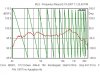
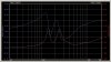
You would simply measure it. If you were using a crossover program like LEAP you would take impedence and phase measurements with the drivers mounted in the cabinets. With a compression driver same thing mounted to the horn on the baffle. You could use any suitable software to do it. You would use these as the impedence curve for drivers you are doing the crossover for. Attached is a measurement for an 035Ti tweeter note how the phase is cycling through 360 degree's. That is from the measurement. Take a look at the other WT2 Imp/Phase measurement. That is what the real driver phase is without the measurement error.

Rob
 

Attachments

  • O35 Phase.jpg
    O35 Phase.jpg
    66.2 KB · Views: 25
  • 035 Ti.jpg
    035 Ti.jpg
    56.9 KB · Views: 28
Jack,
I will be delving into mine fairly soon, but I would like to eliminate the edge surrounding the baffle created by the overlap of the top, bottom and side panels. I think the best way to do that would be to make the appropriate spacer, as you have, but of the required height, and place a new baffle (original one won't work I guess) flat on top of the cabinet sides and top and bottom. I would seal with a gasket and make it removable. But that can't be done if the top, bottom and sides are not pre-cut from PE to be the correct angle to meet a flat baffle. Can you tell me if they are?

I am trying to figure out an easy, low-skill way to do this -- only partially because of reclaiming box volume -- but mostly to have a removable baffle which has no diffraction edges.

PS: I am using PE Classic 8" woofers in a .9 cu ft ported box and they work so well for the money, I am considering the 12" version for this project if my 123A1s don't work.

The edges of the cabinet have roughly a 15 degree slope, so a simple flat panel won't mount on the outer edges and touch everywhere if it is mounted to the front surfaces. An easier way would be to space the front baffle so it mounts inside, and comes up to the outer edges of the cabinet. There would be no diffraction edge top and bottom, since they would be on the same plane as the baffle. The sides will slope back away from that plane at about 15 degrees, and that would probably be better than having a projection sticking out ahead of the baffle.

If you moved the baffle out another 3/8 of an inch further than my sample, it would place the front of the baffle exactly even with the edges of the top, bottom, and sides. There will still be the 15 degree backward slope of the outside edges.
 
Thanks Rob, its just a learning curve thing, I appreciate the time to
make the explaination. I'm starting to see that many of the programs I have downloaded have phase measurement, this is just all very new to me and the learning curve is steep.:yikes:

Ok, enough asking everyone how to swim, I've got to dive in and splash around for a while. Then I'm sure the most obvious will make itself known to me, then I'll be dumbfounded again......:music:

Thanks for the extra patience guys:thmbsp:

Russellc
 
"They are having a problem over there that is phase related, apparently there is such a difference they may only be able to cure it actively, but several ideas have been put forth to address the problem."

I took a look at the measurements posted and it seems they may be confusing Excess phase from the measurement with the actual minimum phase of the drivers. What's posted is the phase response of the driver and the from the measurement together. You need to look at what the driver is doing and ignore the phase anomalies added by the measurement.

Rob:)

Rob,
So minimum phase is what to look at? And should I make this a system measurement through the crossover with all drivers attached in box? I just did this measurement and realized I am confused.
 
The edges of the cabinet have roughly a 15 degree slope, so a simple flat panel won't mount on the outer edges and touch everywhere if it is mounted to the front surfaces. An easier way would be to space the front baffle so it mounts inside, and comes up to the outer edges of the cabinet. There would be no diffraction edge top and bottom, since they would be on the same plane as the baffle. The sides will slope back away from that plane at about 15 degrees, and that would probably be better than having a projection sticking out ahead of the baffle.

If you moved the baffle out another 3/8 of an inch further than my sample, it would place the front of the baffle exactly even with the edges of the top, bottom, and sides. There will still be the 15 degree backward slope of the outside edges.

Thanks, Jack.
That's probably a good "low skill guy" way to do it. Then I can use the supplied baffle. The side gaps might even look good....
 
OK -at a crossroads here

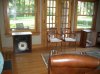
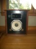
OK, Photos of the latest variation, e-waved Altec Valencias (paid $20 for the empty cabinets) mit der JBL LE-14A's. These just kind of happened by accident, so I don't have a pair of the requisite Selenium drivers - but - I do have a pair of the B&C DE-250's I was reserving for my Santana II, H-811-B, LE120H-1 project. Now there is talk of an upgrade e-wave (Lexus or BMW-wave?) using the B&C drivers. But there is no prepackaged crossover - yet. So am I squandering the B&C's saving them for the H-811-B's? :scratch2: The B&C's are bolt on, but I have a pair of the metal throat adapters.

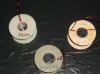
Also, I have several pair of the pictured Altec 23405 coils I'd like to maybe use, but I can't find their rated impedance. Anyone know what it is? These were used in lots of Altec crossovers, Santana II's, even some of the pro stuff.


Altec Valencias 001.jpg

Altec Valencias 002.jpg

Altec Valencias 003.jpg
 
OK, Photos of the latest variation, e-waved Altec Valencias (paid $20 for the empty cabinets) mit der JBL LE-14A's. These just kind of happened by accident, so I don't have a pair of the requisite Selenium drivers - but - I do have a pair of the B&C DE-250's I was reserving for my Santana II, H-811-B, LE120H-1 project. Now there is talk of an upgrade e-wave (Lexus or BMW-wave?) using the B&C drivers. But there is no prepackaged crossover - yet. So am I squandering the B&C's saving them for the H-811-B's? :scratch2: The B&C's are bolt on, but I have a pair of the metal throat adapters.

Also, I have several pair of the pictured Altec 23405 coils I'd like to maybe use, but I can't find their rated impedance. Anyone know what it is? These were used in lots of Altec crossovers, Santana II's, even some of the pro stuff.


View attachment 168861

View attachment 168862

View attachment 168863


Nice. Either get the seleniums, or get the QSC waveguide, bolt the DE 250 to it and play along! Right now, you need the LE14A LP and the HP that goes with it, but change the larger resistor to 16 ohms, so both R! and R2 are 16 ohms. I have the L pad turned way down, like 9:00! its not perfect, but this is the base changes that have been made so far. Zilch's curves show it pretty flat already. Lots of potential here.:thmbsp::thmbsp::thmbsp:

Russellc
 
Thanks, Jack.
That's probably a good "low skill guy" way to do it. Then I can use the supplied baffle. The side gaps might even look good....
Consider how Brandon (augerpro) built his baffles, laminating two layers. Once your front face is flush with the sides, or in front of it, a router with an appropriate size roundover bit will contour the edges toot sweet. :thmbsp:

OK, Photos of the latest variation, e-waved Altec Valencias (paid $20 for the empty cabinets) mit der JBL LE-14A's. These just kind of happened by accident, so I don't have a pair of the requisite Selenium drivers - but - I do have a pair of the B&C DE-250's I was reserving for my Santana II, H-811-B, LE120H-1 project. Now there is talk of an upgrade e-wave (Lexus or BMW-wave?) using the B&C drivers. But there is no prepackaged crossover - yet. So am I squandering the B&C's saving them for the H-811-B's? :scratch2: The B&C's are bolt on, but I have a pair of the metal throat adapters.
That'll certainly work.

Refresh my recollection: were the front baffles removable in your Vals, or did you mod them to have that facility? Others are inquiring as to how to retrofit them with eWave, which may be accomplished with the stock baffles, as well.

You may want to try another round with DE250s on the QSC waveguides and LE14As; it looks like it will all fit nicely. Russell and I are presently listening to them, and Jack, Skywave, and others will have them running shortly and report their findings. The listening comparisons will be interesting, to suggest the least.

What do you experts on the econo-wave think about running 2 of these http://www.parts-express.com/pe/sho...5&FTR=TYMPHANY&CFID=15614973&CFTOKEN=24481813 per cabinet?

I think I will finally build an active bi-amped system if I can decide on the LF section.
Those will almost certainly work. PE is suggesting using singles in an assisted closed-box alignment. If you use them in pairs and run the second as a 0.5 "helper," no assist will be required.... :music:
 
Right now, you need the LE14A LP and the HP that goes with it, but change the larger resistor to 16 ohms, so both R! and R2 are 16 ohms.
Those resistors were selected for the standard eWave highpass filter using 0.47 uF C3. Since the DE250 requires less HF comp than the Seleniums, it'll likely match LE14A nicely. I can try that to confirm. I should probably also run it with 2235H to determine why you're having to dial it back to 9:00.... :dunno:

Thanks Zilch, I am still looking at JBL's and a few other established LF drivers but I like to experiment.
eWave's about encouraging you to experiment. What's "established" here is merely by virtue of others having done exactly that.... :thmbsp:
 
Last edited:
...Refresh my recollection: were the front baffles removable in your Vals, or did you mod them to have that facility? Others are inquiring as to how to retrofit them with eWave, which may be accomplished with the stock baffles, as well.

You may want to try another round with DE250s on the QSC waveguides and LE14As; it looks like it will all fit nicely. Russell and I are presently listening to them, and Jack, Skywave, and others will have them running shortly and report their findings. The listening comparisons will be interesting, to suggest the least...:music:
Front baffles are new, and slip in from the rear. The original Val front baffle was not intended to be easily removable, but a little surgery with a sharp chisel and suitable hammer made it so. New front baffle is 3/4" mdf.

So the standard LE-14 e-wave x-over worth a try with the B&C drivers?
 
Back
Top Bottom