• The move to the new server is done. There are some software and database maintenance updates in process. This has us passing the hat around to help out. We appreciate any donations. Seriously, even a dollar helps. The payment page may be found here - https://www.audiokarma.org/support.html

Zilch's AK Design Collaborative - Econowave Speaker

There are issues, specifically associated with the two drivers generating off-axis interference nulls, total cancellations, in fact, which impinge upon the dispersion pattern. In the normal vertical orientation with the drivers above or below each other, and employing waveguides having asymmetric directivity, the design may position these outside the vertical pattern, or near its edges to augment the forward lobe, but deployed horizontally the nulls occur within the normal listening window, as the angles are fairly narrow, in the range of +/- 20°. Round waveguides force a larger center-to-center distance, narrowing the lobe, as does the higher crossover frequency necessitated by smaller waveguide dimensions.

Scroll down to the end of this description to see the location of the null "eyes" about the axis at the 2kHz crossover frequency in the vertical polar map of this optimized 8" design using an asymmetric waveguide. They would be even closer using a round one:

http://www.eighteensound.com/staticContent/applications/kits/18Sound_kit8.pdf

Hmm, interesting point on the polar response Z. This kind of behavior had not even entered my mind. So I thought about it for a bit and came to the conclusion that while this is certainly an issue with the drivers on the same plane, angling the horn just a few degrees away from the midbass driver might tame a large part of this nastiness, and not be so far away that the midbass would become completely destabilized with regards to proper imaging. Just a thought... I'll think on it more.

And yea, I readily acknowledge that my desire is not strictly for a straight-up econo wave. But since I have become addicted to actives, and since I already have a spare x-over, and since I am planning to get a stereo setup in our main living room -- yes, you read that right, a stereo, NOT a home theater... even though the TV is in the room! The SAF is low with HT stuff. She cannot stand the thought of wires and boxes and amps that make her butt twitch during movies, but she is cool with a sub that delivers booty shaking bass for dancing. Go figure. Anyway, I'm just glad to have an excuse for making a new set of speakers :)
 
Last edited:
I'll think on it more.
It's not about aiming, rather, the different path lengths from the listener to the acoustic centers of the two drivers playing the same frequencies. Whenever those are equal to 1/2 wavelength, they are 180° out of phase and cancel. In the horizontal, as long as the listener is on the vertical axis, they're always equidistant from the acoustic centers.... :yes:
 
Good morning Gents,

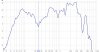
I have been reading this thread for some time now and am thinking about Ewaving a set of Stephens Trusonic 150W 15in woofers that came in their own beautiful enclosure. I have not been able to find any real info about them on the net, however I did take them outside and using REW ran a sweep and am posting the results with no crossover attached outside in my back yard. It is around 33' to a 6' wooden fence.

attachment.php


Do you think this would work?
 

Attachments

  • stephens trusonic outside.jpg
    stephens trusonic outside.jpg
    63.2 KB · Views: 302
It's not about aiming, rather, the different path lengths from the listener to the acoustic centers of the two drivers playing the same frequencies. Whenever those are equal to 1/2 wavelength, they are 180° out of phase and cancel. In the horizontal, as long as the listener is on the vertical axis, they're always equidistant from the acoustic centers.... :yes:

Ok, now I follow. I had to read stuff and learn things so that I understood wth you were saying, but I think I'm getting it now. Round horns have issues. CD horns, like you're using here, were designed to avoid these issues, and despite the lack of vertical coverage I would experience if they are mounted on a horizontal axis, they would still work better. Right?

If I'm following correctly so far, would it be a problem to mildly direct the horns more towards the center of the listening area, both inward and downward a bit from the midbass drivers? I could angle both drivers, too, but the boxes themselves are going to have to stay square to the corners.

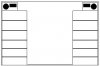
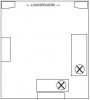
First diagram shows how high and cornered this placement will be. Second shows the relative size of the room, and the X's mark the two key listening positions.
 

Attachments

  • bookshelf.jpg
    bookshelf.jpg
    8.7 KB · Views: 24
  • placement.jpg
    placement.jpg
    9.6 KB · Views: 23
Do you think this would work?
Looks like it. I don't know what that's about at 250 Hz. Do it again with the mic laying on the ground, called "ground plane" measurement, and see if the hole in the response disappears.

If I'm following correctly so far, would it be a problem to mildly direct the horns more towards the center of the listening area, both inward and downward a bit from the midbass drivers? I could angle both drivers, too, but the boxes themselves are going to have to stay square to the corners.

First diagram shows how high and cornered this placement will be. Second shows the relative size of the room, and the X's mark the two key listening positions.
Listening positions are nearly on-axis with the right speaker and 30° to 40° off-axis to the left one. You're going to have to "aim" that one.... :yes:
 
I have a pair of AR 48b's sitting in my basement that I picked up at a thrift a while ago. I refoamed the woofer and midrange and they actually sound pretty damn good despite my amateuristic refoam job. Would these be a good candidate for a waveguide or does the fact that they are 3 way take them out of the picture. Here is what they look like:

DSCN2817.jpg


Crossover points are at 400 and 2500. They have some pretty decent bass with a 10" woofer, 4" mid and dome tweet.
 
Looks like it. I don't know what that's about at 250 Hz. Do it again with the mic laying on the ground, called "ground plane" measurement, and see if the hole in the response disappears.

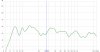
OK here is what it looked like on the floor in the house, didn't feel like pulling all of that out on the deck again.

attachment.php


Thanks

Bill
 

Attachments

  • stephens on the floor.jpg
    stephens on the floor.jpg
    49.2 KB · Views: 271
I must have been asleep yesterday when I announced that the B&C needed a lower hi pass. After changing parts today, and firing it up, it was obvious that 2.2 KHz was too low. Going back to the 2.5 KHz parts also indicated that that was also too low. What gives, he said?

I went back to the standard EconoWave crossover values, and the transition through crossover is smooth and nice. Every bit as nice as the hi efficiency crossover done earlier. I must have connected something wrong after one of the parts changes. Probably hooked the HF backwards. That is the only thing I can figure out that would have yielded the results that were photographed and presented. Oh well. Never mind!

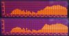
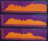
The following FR's show the response of the system with standard E'Wave low efficiency values. The first panoramic pic shows the FR's with normal connections at the top, the FR with the HF reversed in the middle, and the FR of the woofer at the bottom.

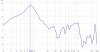
The second FR panoramic shows the output of the B&C at full output on the top, and the Selenium on the bottom. The output was achieved by shorting the attenuation resistor with the L-Pad at maximum setting. The B&C puts out roughly 1-2 dB more volume on the QSC waveguide than the Selenium does on the JBL. Since the attenuation resistor drops the output of the compression driver by a fixed amount, it seems better to redefine the woofers that can be matched, than to recalculate the resistors. Too little attenuation will affect the amount of compensation that can be achieved.

It seems that the B&C will match with a woofer roughly 1-2 dB greater SPL than the Selenium on a JBL waveguide. Therefore the dividing point should probably be greater and less than 97 dB when using the B&C DE250 on the QSC waveguide.

As far as I am concerned, the standard EconoWave crossover will function just fine with the B&C driver/QSC waveguide combination. All that we need is for Zilch to play all the numbers through Spice and see if some small correction is required.
 

Attachments

  • EIIFR's.jpg
    EIIFR's.jpg
    88.9 KB · Views: 34
  • EIIBothFull;.jpg
    EIIBothFull;.jpg
    61.1 KB · Views: 217
Would these be a good candidate for a waveguide or does the fact that they are 3 way take them out of the picture.
It's not mainstream eWave, but there are small waveguides suitable to replace just a tweeter. Kind of a pricey upgrade, tho.

OK here is what it looked like on the floor in the house, didn't feel like pulling all of that out on the deck again.
That looks better, no, with respect to performance in the 250 Hz region?

It's not playing as low as I would expect. Do a nearfield measurement, 1/4" from the center of the dust dome. Your volume will have to be way down for this one, but it will reveal the true limit of the low frequency response, assuming the cabinet is a closed box.

As far as I am concerned, the standard EconoWave crossover will function just fine with the B&C driver/QSC waveguide combination. All that we need is for Zilch to play all the numbers through Spice and see if some small correction is required.
Try R1 = 16 Ohms in the standard crossover, please. My waveguide is not yet mounted in a cabinet, so my findings may not correlate.

Any guess what is happening in the woofer response between 125 Hz and 1 kHz? That dip in the DC300 response was not there in your initial measurements using CX3400.... :dunno:
 
That looks better, no, with respect to performance in the 250 Hz region?

It's not playing as low as I would expect. Do a nearfield measurement, 1/4" from the center of the dust dome. Your volume will have to be way down for this one, but it will reveal the true limit of the low frequency response, assuming the cabinet is a closed box.
:


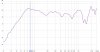
The cabinet has a port that is 12" by 2.5" I tried the measurement as you suggested with the mic (RS SPL meter) just at the front of the port, then 1/4" from the dust cover, and finally 1/4" from the dust cover with the port blocked with a piece of wood wrapped in a T-shirt and held in place.

Mic at Port
attachment.php


Mic at dustcover Port open
attachment.php


Mic at dustcover Port closed
attachment.php


All Three
attachment.php


The box is 3.2 cu. ft. hardwood plywood sides bottom and top 1"MDF front and back. Here is a picture of it with the back off.

attachment.php
 

Attachments

  • stephens in port.jpg
    stephens in port.jpg
    55.5 KB · Views: 236
  • stephens distcover port open.jpg
    stephens distcover port open.jpg
    51.2 KB · Views: 233
  • stephens dustcover port closed.jpg
    stephens dustcover port closed.jpg
    51.5 KB · Views: 234
  • stephens all three.jpg
    stephens all three.jpg
    72.8 KB · Views: 235
Doing the summation in my head, you're got useable bass down to 40 Hz, at least.

If the T/S parameters of that woofer are known, you could model the system in software and maybe improve upon that with optimized port tuning.... :yes:
 
I don't think the T/S parameters are known, at least I was unable to find anything about them. Plenty of info about 150FR's but not so much with the 150W's. I have the selenium drivers and JBL waveguides on the way with the L-pads thanks to rightbrained. Should be able to get started on them soon to give them a ride. I am pretty sure the waveguide will fit just above the woofer where the port is. I could then create a new round port to the side of the woofer. Not too sure how to go about designing the size of the new port. :scratch2:

Any help or direction would be mucho appreciated!

Thanks

Bill

Edit: I know that Jackgiff had done some work with the 150FR in the first few pages of this thread, I don't know if the T/S parameters of the 150FR would be comparable to the 150W? :dunno:
 
Last edited:
*** SNIP ***
The second FR panoramic shows the output of the B&C at full output on the top, and the Selenium on the bottom. The output was achieved by shorting the attenuation resistor with the L-Pad at maximum setting. The B&C puts out roughly 1-2 dB more volume on the QSC waveguide than the Selenium does on the JBL. Since the attenuation resistor drops the output of the compression driver by a fixed amount, it seems better to redefine the woofers that can be matched, than to recalculate the resistors. Too little attenuation will affect the amount of compensation that can be achieved.


*** SNIP ***

As far as I am concerned, the standard EconoWave crossover will function just fine with the B&C driver/QSC waveguide combination. All that we need is for Zilch to play all the numbers through Spice and see if some small correction is required.

To put this in context of the sound, other things being equal the Selenium/JBL combo will sound a little more 'distant' in comparison with the B&C/QSC combo. This is due to the apparent dip in the 'presence' region of 2K - 3K of the Selenium/JBL plot. Speakers with this dip characteristic often sound farther away than speakers with more energy in this region.
Does this account for the reported smoother sound of the B&C/QSC? Possibly. It certainly ought to be audible and will result in a different tonal character.

attachment.php
 
Zilch; said:
Try R1 = 16 Ohms in the standard crossover, please. My waveguide is not yet mounted in a cabinet, so my findings may not correlate.

Any guess what is happening in the woofer response between 125 Hz and 1 kHz? That dip in the DC300 response was not there in your initial measurements using CX3400.... :dunno:

Are you saying to try R1=16 Ohms, R2=16 Ohms, and C3=.47 microfarads?

As far as the dip in the DC300 output, the first FR's in post 7194 shows a dip of around 15 dB. That FR was taken with no fiberglass in the cabinets and a small hole in the back that was unsealed(no small Zilchplugz). Notice that the bass had a notch in the leading edge, and the waveform of the FR was not exactly like the following FR's. I can only surmise that it may have been standing waves in the cabinet that changed the waveform pattern.

Subsequent measurements are all pretty much identical, and show a dip of approximately 10 db. The manufacturers spec sheet on the DC300 show a dip of around 5 dB. 2:1 is probably production tolerance, No?
 
I ordered DC300s, not intended for my home project. But I will have them home to try out with the QSC and measure for a little while.
 
Are you saying to try R1=16 Ohms, R2=16 Ohms, and C3=.47 microfarads?
Yes. That was my preliminary result with the waveguide freestanding; I'd like to get a feel for how much difference mounting it on the baffle contributes.

Subsequent measurements are all pretty much identical, and show a dip of approximately 10 db. The manufacturers spec sheet on the DC300 show a dip of around 5 dB. 2:1 is probably production tolerance, No?
I'm referring to how the DC300 performed here:

http://www.audiokarma.org/forums/showthread.php?p=3042949#post3042949

The implication being that the lowpass may need to be customized for that woofer.... :dunno:

380038/7334=51.8187​
 
Jack I tried that and it lifts the compensation in the upper end...looks flatter. I did not take readings of each driver alone, but will do now that I got some fill in the box.

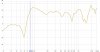
That looks pretty flat, but it isn't the way to go unless you have special reasons for mistuning the HF compensation. I tried doing 16, 16, and .47, and here are the results as the L-Pad is varied. The compensation droops as the L-Pad level is reduced. If your woofer requires you to lower the L-Pad setting, it isn't so flat any more.

The value of R1 is what sets the attenuation level of the tweeter. R2 is to restore the impedance seen by the hi pass to exactly what it would have been before R1 was added. C3 of course does the HF compensation.

To achieve less compensation, C3 should be made smaller. Changing R1 to get less compensation is not doing what you think it is. While the apparent compensation at some setting may indeed be less, the HF driver sees less attenuation. That means setting the L-Pad lower, which causes more droop.

I would try making the value of C3 smaller to get less compensation, not reduce the Value of R1, because that changes the attenuation to the driver and messes up the phase relationship as the L-Pad is varied..

The top FR shown is at max setting of the L-Pad, the middle is at normal listening level, and the bottom is the setting for lower SPL woofers.
 

Attachments

  • EconoII16-16FR's.jpg
    EconoII16-16FR's.jpg
    103.9 KB · Views: 29
Yes. That was my preliminary result with the waveguide freestanding; I'd like to get a feel for how much difference mounting it on the baffle contributes.

I'm referring to how the DC300 performed here:

The implication being that the lowpass may need to be customized for that woofer.... :dunno:

380038/7334=51.8187​

I don't know how much difference baffle mounting would do for the waveguide. I can't believe it would matter that much. My measurements of 16, 16 and .47 are shown above. If less compensation was desired, and also less attenuation, I would simply change the 1.5 microfarads on the standard >95 dB crossover to .47. That wouldn't upset the phase relationship nearly as badly as just changing the 30 ohms to 16 ohms.

That is the post I referred to. I see 15 dB difference between the lowest and the highest (80Hz and 630 Hz), and the pattern is different. Even throwing away the deepest lows, the change appears to be about 10 dB. The thing of notice is that the increase at the end of the woofers range is missing in this bi-amped FR. I am sure that is because it is being driven with a low impedance amplifier output, not a low pass filter. Maybe a Zobel would cure that. That is something that will be tried.
 
Last edited:
Back
Top Bottom