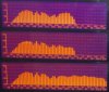
I'm less concerned about what's happening with DC300 at 80 Hz, which can be adjusted with box tuning, once we characterize it accurately and decide what is desired, than with the 5 dB "hump" between 800 Hz and 2 kHz, clearly shown in your curves just above, smack in the middle of the target acoustic crossover region. I don't believe the highpass can be finalized until that is mitigated, and I suspect it can be done just by adjusting the lowpass components, as was done with LE14A.
With respect to the HF comp, we understand it differently. By my view, C3 sets a fundamental 6 dB/octave slope beginning at some frequency above 20 kHz according to the impedance of the driver; a lower value starts that sloping downward at a higher frequency, establishing the overall attenuation in the frequency range of interest. R1 varies the slope, and thus the compensation and attenuation simultaneously. I do not understand the role of R2 entirely, but he explains that in his tutorial, which I will review again.
In any case, here is his attenuation chart and the results I got using those values with Selenium D220Ti on the JBL waveguide and the eWave highpass, as posted earlier in this thread:
http://www.audioroundtable.com/PiSpeakers/messages/1278.html
The discussion begins ~Page 140 in this thread. Notes from Wayne:
1) He chooses R2 in combination with the basic highpass filter such that the rolloff is underdamped. Looks like we may need some of that.
2) He cautions that an L-pad may not be the optimum means for accomplishing attenuation. We want one, and optimize accordingly. For any given C3 value, it's clear that his R1/R2 selections generate slightly different curves. 16/16/0.47 is one of those on his chart, -10 dB. When I do this, it's with the L-pad at mid level or above to establish the desired attenuation, and the curve is always different in detail when it is set to Max, i.e., effectively out of the circuit.
I should repeat that study with the DE250 on QSC waveguide to see where we are by comparison....