• The move to the new server is done. There are some software and database maintenance updates in process. This has us passing the hat around to help out. We appreciate any donations. Seriously, even a dollar helps. The payment page may be found here - https://www.audiokarma.org/support.html

Zilch's AK Design Collaborative - Econowave Speaker

Good one George. Interesting that the foams on these don't rot, they harden. My are fairly hard but I don't know if they need refoam or not. Bauhausler is helping me out in my 6SL7/2A3/GM70 amp build at the moment, so I think these L77 need to go on the back burner. When I get to them though (if I keep them) I will do as you did George but with the small waveguide and the standard eWave crossover.......for the less sensitive woofer of course.
Looks like the 8" square PT waveguide will fit nicely.... :thmbsp:
 
That's what I was thinking Z. Do a 3/4 walnut motor board and refinish the cabs to match. It'd be a good one.
 
Isolated

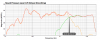
OK, I re-measured using 8 Ohm non inductive resistors as dummy loads in place of drivers.

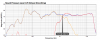
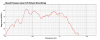
These are taken with DE250 on QSC on top of PE KD Trap box loaded with JBL 123A-1. Crossovers are standard EWave (30 Ohm comp) and 4Pi with additional fixed attenuation plus L-Pad and a notch filter to take the top down some.

Zobel is 8 Ohm/20uF, what Wayne usually uses.

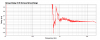
EWave orange: LF; green: HF; red: sum
attachment.php


EWave blue: LF w/Zobel; orange: LF w/o Zobel; purple: sum w/Zobel
attachment.php


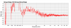
4Pi yellow: LF; red: HF; blue: sum [standard 4Pi Zobel in line]
attachment.php


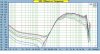
4Pi orange: w/Zobel; red: w-o/Zobel
attachment.php


Seems like the Zobel has to work more at about 1.8k for this woofer.
 

Attachments

  • EW LF:HF:Sum.png
    EW LF:HF:Sum.png
    57.6 KB · Views: 455
  • EW LF:LFwZob:sum w Zobel.png
    EW LF:LFwZob:sum w Zobel.png
    54.9 KB · Views: 331
  • 4Pi w:Zobel- LF:HF:sum.png
    4Pi w:Zobel- LF:HF:sum.png
    58.6 KB · Views: 452
  • 4Pi LF w:w-o Zobel.png
    4Pi LF w:w-o Zobel.png
    45.8 KB · Views: 329
Last edited:
Distortion

Don't know if this is meaningful, but here are distortion measurements of DE250 on QSC. HF shown with the lower crossover point and the higher crossover point. Listening, I think it sounds OK crossed at the lower frequency. I have to listen more because I just set up a pair last night.

Red is 4pi, blue is EWave.
attachment.php
 

Attachments

  • de250 distort:EW:491.png
    de250 distort:EW:491.png
    64.7 KB · Views: 511
Presto changeo...

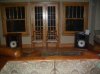
LE14A, B&C DE250s, QSC waveguides, A series Valencia cabs. LE14 x-over varient. Songs In The Key Of Life playing...


Altec Valencias.jpg
 
Last edited:
Just to be clear, I think the solid curves shown below are the fundamental sweep of the tweeter circuit by itself, the dotted curves (next down) are 2nd harmonic and the dashed lines (third down) are 3rd harmonic. Can you verify this please?

P.S. haven't had time to check in much in the past few weeks. Looks like you guys have been having some fun!

Don't know if this is meaningful, but here are distortion measurements of DE250 on QSC. HF shown with the lower crossover point and the higher crossover point. Listening, I think it sounds OK crossed at the lower frequency. I have to listen more because I just set up a pair last night.

Red is 4pi, blue is EWave.
attachment.php
 
OK, I re-measured using 8 Ohm non inductive resistors as dummy loads in place of drivers.
You have identified the culprit and how to deal with it. :thmbsp:

Looks like Wayne will have some comments; I'll have some, too, once I study it a bit more.

LE14A, B&C DE250s, QSC waveguides, A series Valencia cabs. LE14 x-over varient. Songs In The Key Of Life playing...
Very nice!

Do you consider DE250/QSC a significant upgrade with respect to the performance?
 
Last edited:
You have identified the culprit and how to deal with it. :thmbsp:

Looks like Wayne will have some comments; I'll have some, too, once I study it a bit more.

Very nice!

Do you consider DE250/QSC a significant upgrade with respect to the performance?

Well, they certainly sound good to my ear. I'm not using anything that would be confused as a serious reference system to drive them, almost embarassingly low tech, really, so I don't really know how good they may ultimately be. I've got my three other ewave varients spread out on the second & third floors, so a direct A-B comparison is not possible. I bought the B&C drivers to use on my Altec H-811B horns, so my standard here was that the QSC waveguides would be an upgrade from that, and I believe they are.

The electronics side of this particular setup is dictated by continued domestic tranquility, and as such, what can be hidden in the 12 inch deep, 1925, built-in cabinets at the opposite end of the room. So what fits the bill, and the cabinet, is an old Bose Lifestyle AM/FM/CD head unit used as a preamp/tuner/CD player that feeds a Carver M400 cube. The Bose has a RF remote, so I can run the thing from the veranda, etc.
 
Just to be clear, I think the solid curves shown below are the fundamental sweep of the tweeter circuit by itself, the dotted curves (next down) are 2nd harmonic and the dashed lines (third down) are 3rd harmonic. Can you verify this please?

P.S. haven't had time to check in much in the past few weeks. Looks like you guys have been having some fun!

Yes, Wayne, you are correct all around. :)
Since you may not have been following, to be clear, when I say "4Pi" it is not referring to your speaker, but the crossover which I am using as a standard reference on the DE250/QSC waveguide; the woofer in the last post was the JBL 123A-1. I had to use the 20 dB of attenuation derived from your chart, plus an L-pad. (Have to learn Spice.) I know the HF is not optimized. The Econowave crossover is the standard version.
http://www.audiokarma.org/forums/attachment.php?attachmentid=151281&d=1242968714
 
Last edited:
Hi Sykwave,

- It's nice to see you putting your software through it's paces . :thmbsp:

attachment.php


- If you can, see if you can subtract the propagation delay from your pic before displaying it one more time ( it seems to be @ 1.5 ms ) .

- I do feel that Group Delay figures into the lower limits that a horn/driver combo can be used to . But, I also feel that a drivers' Fs plays into this topic / though I've never seen its' contribution studied outright ( the 288 has a very low Fs ) .
- I haven't seen any conclusive work in this area / just a lot of anecdotal claims ( just like my post that you referenced above :D ) .

- Fortunately, like most things in audio , nothing's written in stone .
- FWIW, I'm interested in this waveguide ( for SR work ) / so I do appreciate all the postings made, concerning it .

>< cheers :)
 
Last edited:
OK, Earl, I removed flight time and I zoomed in more.

Trying to get a grasp of scaling in this software, and the big thing is interpretation. Thanks for your input.
:)
attachment.php
 

Attachments

  • 4Pi:De250:QSC GD HF zoom.png
    4Pi:De250:QSC GD HF zoom.png
    70.6 KB · Views: 500
Horns become more resistive in their passbands, but down low they become increasingly reactive. This can be described in many ways, as group delay, acoustic phase, etc. A horn's ability to be resistive can be seen as a measure of quality, because horns that provide better acoustic loading are more purely resistive. The impedance curve also shows how smooth the termination is.

All drivers have some reactance, whether direct radiator or horn. Horns are usually resistive over a wider range than most direct radiators, but they also usually have more peaks and dips in their impedance curve. Each device is resistive at certain frequencies, and some are more purely resistive than others. This is reflected in the electrical impedance as well, and that's why speaker drivers aren't purely resistive loads. It is usually important to take account the real impedance when designing a crossover, because the load reactance is a part of the filter, and modifies the transfer function compared to a purely resistive load.

While not specific to midrange or tweeter horns, the post below shows the impedance of a bass horn, including the real (resistive) and imaginary (reactive) parts. These two are 90° apart, so total impedance is a vector. This is not limited to basshorns, but applies to all horns.

 
OK, I re-measured using 8 Ohm non inductive resistors as dummy loads in place of drivers.

These are taken with DE250 on QSC on top of PE KD Trap box loaded with JBL 123A-1. Crossovers are standard EWave (30 Ohm comp) and 4Pi with additional fixed attenuation plus L-Pad and a notch filter to take the top down some.
Your measurements agree with my own and Jack's with respect to the DE250/QSC on the eWave highpass -- the green line. It is slightly overcompensated and the core frequency is too high, the latter being the primary reason the crossover has moved up to 2.2 kHz. Is this with R1 = 30 or 16 Ohms? Crank the high SPL up 4-5 dB and you'll be the same place as me, ~1.8 kHz.

attachment.php


attachment.php


attachment.php

See Geddes's horizontal polar for how we'd like it to be looking, his green line:

attachment.php

We're very close; we just have to move it lower by adjusting the core filter.

The 4-Pi highpass, the red line, is more overcompensated and underdamped. The culprit at 1.8 kHz is 123A-1. Wayne's lowpass knocks that down, orange, but not optimally, perhaps; the apparent flat response through the crossover region is coming from the underdamped HF driver making up the difference, an effective 4 dB of "boost" in a region below the recommended minimum crossover frequency for the DE250. Once the comp is tweaked, we'll not want that to remain. The fact that red is above blue there indicates the flat response is the result of a phase cancellation:

attachment.php


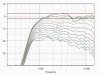
It'd be nice to get it playing well down there at 1.2 kHz (that's where Geddes uses it in Abbey, I believe), but the QSC is losing pattern control that low according to Brandon's polars, both in the horizontal:

attachment.php

And the vertical:

attachment.php

http://sites.google.com/site/drivervault/driver-measurements/horns-and-waveguides/qsc-pl-000446-gp

Much as we'd like the crossover to be lower, I'd prefer to stay with our 1.6 kHz target 'til we see where the vertical nodes come in; once that is known, we may be able to fine-tune a compromise, but the C/C distance is against us in accomplishing that with this waveguide.... :yes:

 

Attachments

  • Geddes ESP 12.jpg
    Geddes ESP 12.jpg
    90.6 KB · Views: 277
  • QSC Horizontal.jpg
    QSC Horizontal.jpg
    85.9 KB · Views: 275
  • QSC Vertical.jpg
    QSC Vertical.jpg
    85.7 KB · Views: 274
Last edited:
That's 30 Ohms, Zilch.

I see, cranking the HF brings the acoustical x-o down...follow the lines.

Everything you said makes sense.

Since there are so many potential woofers out there to build with, I assume the generic 1.2kHz EWave low pass will remain.

I'll try to hit the mark on the 123A-1 Zobel and take it from there.
Unfortunately, I took the DC300s to school today for the dumpster bin EWaves.
 
Since there are so many potential woofers out there to build with, I assume the generic 1.2kHz EWave low pass will remain.
Assuming we keep the highpass in the original place, yes; it's the high frequency we've got to "lock." It's the universal module having a defined response characteristic with which an array of suitable woofers may be adaptively mated.... :yes:
 
It is slightly overcompensated and the core frequency is too high, the latter being the primary reason the crossover has moved up to 2.2 kHz. Is this with R1 = 30 or 16 Ohms? Crank the high SPL up 4-5 dB and you'll be the same place as me,


We're very close; we just have to move it lower by adjusting the core filter.

How are you adjusting the core filter? you mean the crossover point?

It'd be nice to get it playing well down there at 1.2 kHz (that's where Geddes uses it in Abbey, I believe), but the QSC is losing pattern control that low according to Brandon's polars, both in the horizontal:

May just be the way it is with this waveguide.....

Much as we'd like the crossover to be lower, I'd prefer to stay with our 1.6 kHz target 'til we see where the vertical nodes come in; once that is known, we may be able to fine-tune a compromise, but the C/C distance is against us in accomplishing that with this waveguide.... :yes:

:lurk:
Russellc
 
Greetings gentlemen,

I may very well be joining the ranks of the E-wavers in the near future but I have some questions about an unusual way to go about it. I have no cabs (although I've been on the lookout for some) that will allow me accomplish the normal woofer/horn arrangement. My speakers are DCM TF-600s. My hopes are that I can acheive acceptable results by affixing the horn to the top of the DCM and using an active crossover to biamp. The DCMs would not be altered in any way but the LF would be sent to them. Would this present any showstoppers as far as you fellows can see?

Also, I have yet to acquire an active crossover but I have my sights on a Crown VFX2A. Any opinions on this unit?
 
Back
Top Bottom