jackgiff
Well-Known Member
Why did you raise the crossover point to 1.8 KHz?



Not by preference; I'd sure be happier if it were down around 1.5 kHz. I put up the EconoWave PCD Challenge over on the Tech Talk forum:Why did you raise the crossover point to 1.8 KHz?

The feet are from parts express.

Edit: Now with a 3/4" roundover of the woofer opening:
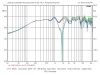
I haven't rerun the vertical polar map, but it's unlikely to have altered that. You can see the on-axis effect in the plot above -- about 1/2 whit worth of difference, and mostly in the high frequencies. Until proven otherwise, I calling it an "aesthetic" variable.What did that do for the Measurements before and after? Did it help the forward lobe?
 ]
]
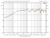
I haven't rerun the vertical polar map, but it's unlikely to have altered that. You can see the on-axis effect in the plot above -- about 1/2 whit worth of difference, and mostly in the high frequencies. Until proven otherwise, I calling it an "aesthetic" variable.
[Maybe 1/8 whit at 400 - 500 Hz....

Not by preference; I'd sure be happier if it were down around 1.5 kHz. I put up the EconoWave PCD Challenge over on the Tech Talk forum:
http://techtalk.parts-express.com/showthread.php?t=215536
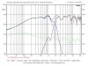
It's a juggling act, much as Wayne describes: woofer with heavy resonance in the XO region, acoustic center offsets, wide C/C spacing, and necessity to precisely aim the forward axis due to consequential narrow spacing of the vertical nulls.
I've posted my FRD and ZMA files over there. The eWave XO will model in PCD with a few tricks. There's no constant directivity HF model, so use a small tweeter piston diameter, like 1", perhaps....
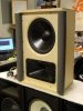
Edit: Now with a 3/4" roundover of the woofer opening:


Definately looks more finished, whether it sounds better or not!:yes:
Russellc
We're going to do more, like move the baffle incrementally forward, now that we have a stable baseline. I am anticipating some surprises; there is no dearth of blather about baffle edge diffraction, but precious little data.It does indeed. I'd be tempted to run a roundover bit (might need a smaller radius) all around the protruding front edges. Wonder if that would be a measurable diff?
Yup, at least one whit there, but elevated methane levels might account for it....Is it just me, or is there a whole whit there at 7K?

...Yup, at least one whit there, but increased methane levels might account for it....
Hmmm. Don't know how to do that.I am running the 2 4 ohm CV's in series, but in a 2.5 mode with the mids filtered out of the bottom "Helper" woofer.

SO, what happens to the forward axis and crossover frequency as we adjust the L-pad up and down?...
I'm calling it "stable and predictable."
Hmmm. Don't know how to do that.
A cap across the bottom one...? :scratch2:
Yes, and unless you're modeling the L-pad as well, include one at the desired nominal setting when measuring the impedance and frequency response of the HF driver. In PCD, we're a resistor short of being able to put one in the model with eWave HF comp topology.Edit:I should have realized that "on paper" sensitivities aren't the whole story, driver/waveguide combo must be measured acoustically for output.
Did you build from the plans I posted several years ago on LHF?I'm hoping the pair of 2226's I just got will make my home-built TCB really rumble!
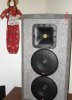
That's going to work, too, I bet, and constant directivity will make a major difference.Next up is a set of D-130 floor monitor's that are going to have the 2402's replaced by the 6X6 WG... The hole in the mids was actually helpful with live mics close by, but otherwise they sound like "boom-TSSSH" (Note lower case 'Boom", they are 130's after all!)