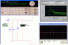
It's just an AC signal generator and measuring the voltage. Set the vertical scale for dB magnitude and the horizontal for log frequency.
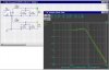
You can see I merely duplicated the circuit and used two test points to compare the performance with a different value C4.
I could adjust L2 now and match the frequency with different damping at the crossover point. With more tweaking, I could get the slopes to superimpose, if that were the objective.
Then, I put the revised values in the prototype, measure the new performance in comparison to the original, and see if works worth a whit accomplishing what I intended.
Is there a problem here? Yeah, two major ones:
1) The driver's not a resistor; you've got to use an accurate model of the specific one you've got for the transfer function to really be correct, and,
2) It's the acoustic response that counts. That's what you're controlling with the filter voltage drive, but it's very likely not the same. More sophisticated tools than SPICE are required to sim that, but measurement works, too.
I call this "The Hard Way," but have created many successful filter designs using it....




 I wish I could find a pair of those compression drivers cheap:thumbsdn:

 ity:
ity: