

You are using an out of date browser. It may not display this or other websites correctly.
You should upgrade or use an alternative browser.
You should upgrade or use an alternative browser.
across the bench: an electronic menagerie of diagnostic oddities plus photos and design analysis
- Thread starter sae-7125
- Start date

sae-7125
Super Member
the oddball resistor connecting to nothing.

r8 on the right channel amp board looks like it might have had a top side wire connection or something. no stray wiring to be found.

but there is clearly no connection to a pcb trace on the solder side, seems odd indeed.
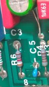
c5 was replaced in an attempt to reduce the channels tendency to go into oscillation. original cap measured a little over 7pf, should be 5pf and now there is a fresh 4pf installed. r8 is photo bombing on the left side.
r8 on the right channel amp board looks like it might have had a top side wire connection or something. no stray wiring to be found.
but there is clearly no connection to a pcb trace on the solder side, seems odd indeed.
c5 was replaced in an attempt to reduce the channels tendency to go into oscillation. original cap measured a little over 7pf, should be 5pf and now there is a fresh 4pf installed. r8 is photo bombing on the left side.
sae-7125
Super Member
oscillation waveform and thermal outcome.

when the amber series 70 amp channel goes into oscillation, dim bulb safety net active otherwise the dc bias would go as high as it wants (until the outputs pop). looks like a 4.5us wave which is 222khz vs dmm reading 680khz.
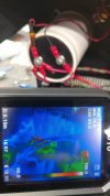
r16 (2.7r 1w) carbon comp starts to heat up when the amp goes into oscillation. once again the bulb safety net is holding back the fire.
when the amber series 70 amp channel goes into oscillation, dim bulb safety net active otherwise the dc bias would go as high as it wants (until the outputs pop). looks like a 4.5us wave which is 222khz vs dmm reading 680khz.
r16 (2.7r 1w) carbon comp starts to heat up when the amp goes into oscillation. once again the bulb safety net is holding back the fire.
sae-7125
Super Member
yet another build quality concern.
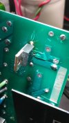
one of the drivers (2sb633) must have had some installation issues at the factory judging by the potential rework damage. note the lifted/warped pcb trace, at least they used wide thick traces for most of the circuit. also something to notice is the trace deletion (factory) most likely due to a design revision, pcb bald spot.
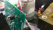
this is after desoldering the component without trashing the plated through-hole. we now see that the bottom trace was severed from the through-hole at some point in time. there is a functional electrical connection between top and bottom trace since solder flowed to the top of the board.
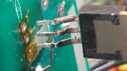
another view of the detached trace. interesting to see pcb surface scratches point towards the three holes. person on the build line was feeling their way across the boards surface until the part fell in.
i wonder how many other amber amp assemblies have similar issues. another schematic issue looks to be capacitor polarity as it relates to dc rails but i should probably stop looking at that particular document as i will only notice more errors.
one of the drivers (2sb633) must have had some installation issues at the factory judging by the potential rework damage. note the lifted/warped pcb trace, at least they used wide thick traces for most of the circuit. also something to notice is the trace deletion (factory) most likely due to a design revision, pcb bald spot.
this is after desoldering the component without trashing the plated through-hole. we now see that the bottom trace was severed from the through-hole at some point in time. there is a functional electrical connection between top and bottom trace since solder flowed to the top of the board.
another view of the detached trace. interesting to see pcb surface scratches point towards the three holes. person on the build line was feeling their way across the boards surface until the part fell in.
i wonder how many other amber amp assemblies have similar issues. another schematic issue looks to be capacitor polarity as it relates to dc rails but i should probably stop looking at that particular document as i will only notice more errors.
sae-7125
Super Member
this amp has the original outputs and driver transistors.
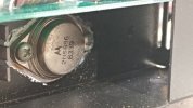
2n5686 and its complement 2n5684.
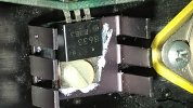
2sb633 and its complement 2sd613. for the right channel both updated to mje15028/29.

final testing soon and then the amber should be done.
2n5686 and its complement 2n5684.
2sb633 and its complement 2sd613. for the right channel both updated to mje15028/29.
2SB633 datasheet(1/3 Pages) SANYO
Datasheet search, datasheets, Datasheet search site for Electronic Components and Semiconductors, integrated circuits, diodes, triacs and other semiconductors.
www.alldatasheet.com
final testing soon and then the amber should be done.

Great to hear you are nearing completion with the Amber.
Great documentation of your process.
Soon, you will be able to push some music through; and let us know how she sounds.
We can only wonder what will cross the bench in the upcoming days ....
Great documentation of your process.
Soon, you will be able to push some music through; and let us know how she sounds.
We can only wonder what will cross the bench in the upcoming days ....
sae-7125
Super Member
a few updates for the amber, it works and is stable and has an emitter resistor mismatch (factory design??) and only with the right channel. bit of a bias difference between 0.22r vs the 0.33r that i found installed. might be due to the right channel "switch" for mono/bridged mode. something to note about the amp... dont expect full 20-20k hz ability, the highs start to drop starting around 12khz and is almost nonexistent by 16k-17khz. so not a hifi/audiophile amp in term of full spectrum, amp could be useful for sensitive tweeters+ears (reduced harshness) which explains why some reviews indicate "tube like" performance.
a few more photos to sort through before the final batch gets posted. next up will be citation sixteen power amp and its LED vu array.
a few more photos to sort through before the final batch gets posted. next up will be citation sixteen power amp and its LED vu array.
sae-7125
Super Member
and now the final batch of amber photos, closing out the repair file and now its sitting on the outbox shelf.
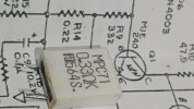
the original r14 from the right channel vs what the schematic says. this resistor also exhibited some weird thermal reactions while in circuit vs measuring normal out of circuit. the new replacement will be 0.33r since that is what the factory installed for some odd reason. thermally, just another quantum oddity for someone to evaluate who has access to an electron microscope...
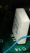
r14 that is in the left channel, same as schematic.
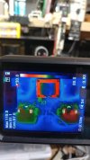
after running the amp for a while there was a thermal imbalance i.e. dc bias needs to be dialed in.

no more weird noise artifacts or glitches or fuzzy caterpillar output waveform. wasnt able to capture a suitable waveform example of frequency vs amplitude in regards to the limited bandwidth of the amp. a simple sweep with a tone generator will highlight the design limitations.

10r input grounding resistors cleaned up instead of the tack welded temp connection.
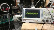
looks like around 50mv of ripple present on the mains caps, larger capacitance value will help reduce if desired.

and here is the happy little amplifier ready for pick up. lots of diagnostic notes and design headaches were documented about this one.
...next...
the original r14 from the right channel vs what the schematic says. this resistor also exhibited some weird thermal reactions while in circuit vs measuring normal out of circuit. the new replacement will be 0.33r since that is what the factory installed for some odd reason. thermally, just another quantum oddity for someone to evaluate who has access to an electron microscope...
r14 that is in the left channel, same as schematic.
after running the amp for a while there was a thermal imbalance i.e. dc bias needs to be dialed in.
no more weird noise artifacts or glitches or fuzzy caterpillar output waveform. wasnt able to capture a suitable waveform example of frequency vs amplitude in regards to the limited bandwidth of the amp. a simple sweep with a tone generator will highlight the design limitations.
10r input grounding resistors cleaned up instead of the tack welded temp connection.
looks like around 50mv of ripple present on the mains caps, larger capacitance value will help reduce if desired.
and here is the happy little amplifier ready for pick up. lots of diagnostic notes and design headaches were documented about this one.
...next...
sae-7125
Super Member
inspecting a large power amp by harman kardon.
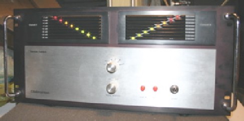
 hifi-wiki.com
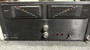
citation sixteen amp, looks like it was stored in a barn that had high humidity judging by all the rust.
even the face plate could use some TLC and elbow grease.
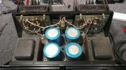
accumulation of particulate matter and contamination on the boards, this amp will need some cleaning first.
 www.audioservicemanuals.com
Inside-Out: Harman Kardon Citation 16 Amplifier - HighFidelityReview - Hi-Fi systems, DVD-Audio and SACD reviews
Look inside of Citation 16 - Harman Kardon's prestige line amplifier
www.highfidelityreview.com
Harman/kardon Citation Sixteen | hifi-wiki.com
citation sixteen amp, looks like it was stored in a barn that had high humidity judging by all the rust.
even the face plate could use some TLC and elbow grease.
accumulation of particulate matter and contamination on the boards, this amp will need some cleaning first.
Free Audio Service Manuals - Free download harman kardon citation 16 service manual
Read or download harman kardon citation 16 service manual PDF with 20 pages. No login, no charge and no limit.
www.audioservicemanuals.com
sae-7125
Super Member
some interesting links with consolidated info for the citation.

 www.head-fi.org
*mentions citation 16 vs 16a, the amp i am inspecting appears to be a 16 with the input chip.
sound technology 3200a audio analyzer in the video.
 www.diyaudio.com
Need replacement for UA739PC opamp. Can anyone help?
It can be replaced with a NET725 but I would rather upgrade the opamp not just replace it. The opamp goes in a driver board for a Harman Kardon citation 16. Any help is appreciated. Thanks. G
www.head-fi.org
Thoughts or tips for Harman Kardon Citation 16 rebuild
Hi Everyone, I recently purchased a HK Citation 16 to replace my current main amp but, I want to give her the royal treatment before she becomes my main amp (it's kinda ugly and beefy maybe it's a him? haha) I'm going to replace all the electrolytic capacitors, trim pots, output...
audiokarma.org
Harman Kardon Citation 16 & 17 Repair->Upgrade
Im newish to rebuilding electronics but can handle a soldering iron and can do some troubleshooting. I just bought a Citation 16 amplifier and a Citation 17 Preamp. The 16 has a blown right channel so that will be the first step to repair. I believe the issue is shorted output transistors. What...
audiokarma.org
sound technology 3200a audio analyzer in the video.
Sound Technology 3200B/3100A info (schematics, etc) anyone?
Looking for schematics, update tips, manuals, etc. for Sound Technology 3200B Analyzer and 3100A Generator. I'm guessing these are pretty old ... late 1980's? Not much at Sound Technology website: history Anybody know anything they can share (Richard, Demian)? thanks, mlloyd1

Bill Ferris
Lunatic Member
I think he indicated that the .33 output transistor current sharing resistor, (though measuring, via his ohmic checking out of circuit with meter, changed), within % limits with the amp being driven into a load, the resistor dynamically changed it value in such a manner as to cause the HF frequency bursts to appear on that channel`s sinewave.What ended up being the cause of the oscillation on the Amber?
At least, that`s what I understood from his follow up post.
sae-7125
Super Member
after changing out the right channel drivers, from 2sb633/2sd613 to mje15029/28, the sensitivity to go into oscillation decreased substantially. i started with a recap when doing repairs which had no effect and therefore a bad cap can be ruled out as a primary suspect. beneficial info for future amber repairs. c5 on pin 3 of the LM391 had little effect at reducing the oscillation reaction. parallel input diodes 1n914 had an effect on the oscillation magnitude but it was still possible to trigger it after the update.What ended up being the cause of the oscillation on the Amber?
the r14 emitter resistor may have been a catalyst that caused a driver transistor to go into oscillation.the .33 output transistor current sharing resistor
since the LM391 has pin 9 directly connected to speaker output (before r17 parallel resistor+inductor) it functions as a feedback input which explains why any simple transient injection (dmm probe connected to nothing and tapping the probe tip on the speaker output terminal) would cause a reaction which sends the bias into overload territory.
also, floating the digital scope (2 prong mains adapter) and tapping the speaker output terminal with the scope probe ground wire was highly effective in triggering the oscillation. dim bulb (for the win) helped to reduce any potential carnage, like the outputs blowing up.
in summary, it would appear that multiple components helped to create a sensitivity towards high kilohertz oscillation output. in future if i see another amber with similar issues my first repair attempt would be both drivers and then test for oscillation sensitivity (no recap at the beginning). process of elimination is slow to achieve results but when it does... future diagnostics become much easier. always a learning curve on the first time of a particular make/model of electronic device. now i know exactly what to look for in future.
now this is assuming the LM391 doesnt have any unique quirks or unilateral idiosyncrasies but doing the channel chip swap proved the overall board circuit had gone out of tolerance somewhere and so the chip is not on the top ten most wanted gremlin list, yet. its hard to piece together a game plan when the schematic has issues, plus the chip data sheet.
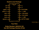
LM391N-100, assuming anything on the datasheet is accurate.
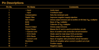
explanation of each pins function on the LM391.
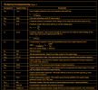
component value suggestions and calculations for the LM391.
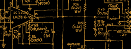
a "rough draft" copy of the schematic dated 12-nov-84 which is probably newer than the production date of this amp on the bench. newer models might have had a few circuit mods vs '83 and older, or something since this is all speculation on my part.

There must be a reason that LM391 wasn't more widely used, and perhaps a tendency towards oscillation is one reason why. Might be one reason the HF response on that amp is so thin also, seems that it's part of the feedback network.
Anyhow, excellent work tracking that down!
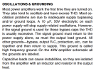
edit - the app note for the LM391 goes into specific grounding requirements
Anyhow, excellent work tracking that down!
edit - the app note for the LM391 goes into specific grounding requirements
Last edited:
sae-7125
Super Member
excellent observation. even though the chip wasnt rooted out as a primary cause it is however at the center of the entire circuit. amber did not use all the pins on the chip, looks like pin 4 was neglected not to mention some of the component deletions between c10 and r19 shown earlier.There must be a reason that LM391 wasn't more widely used, and perhaps a tendency towards oscillation is one reason why.
i did not measure to see if pin 4 is naturally shorted to another pin via a pcb trace or if it was left floating at "any" potential. either way the LM391 might be an "extremely sensitive to work with" type of device which requires lots of time and resources to design around properly. the 5 band color code resistors would indicate some attention was placed on component tolerances but they may not of accounted for transistor hfe/current drift as they age and the chip runs moderately hot (around 120f if i remember after demo testing) which does not promote chip longevity.
semiconductors drift out of tolerance for most things, big question is can the rest of the circuit handle the variance and still function reasonably well.
with the emitter resistor imbalance on the right channel exclusively, that will cause uneven heating of the driver and output transistor as well (0.33r vs 0.22r). just another design fly in the circuit ointment.
Wanna help with computer repair before I throw this thing through the window --- Just kidding ....
I wore the computer tech hat for much too long --
Working on issues, and my provider is the one at fault for my Primary LONNNNNG ongoing issue ---
Call Guard -- sees vital calls as SPAM RISK...
just about wants me to join all the regular social media crap and scream bloody f'in murder.
Now I have no E-mail ---
"Sorry we don't provide support for third party Email clients'
I remember telling folks the VERY same thing --
Ugh --
KinDa like the Amber Amber amp == Figure it out yourself --- and MAYBE it will work -- unless MIcrosoft now owns me ....
/Rant over ---
Thank you for your Oscillation information
I don't find @w3jn was out of the ordinary in his question, sometimes clarification allows others (like me to revisit) and push the concepts deeper into the mind
I do say-- since my crazy Internet BS --- and tech support that a lot of these guys no NOTHING about pisses, me off the most ---"Dude You need a new Modem" NOT.
The first place I return to is the Menagerie ---
STILL NO EMAIL for chrissake.
onward we plod --- My very own Amber Amp indeed. ... yeesh!
I wore the computer tech hat for much too long --
Working on issues, and my provider is the one at fault for my Primary LONNNNNG ongoing issue ---
Call Guard -- sees vital calls as SPAM RISK...
just about wants me to join all the regular social media crap and scream bloody f'in murder.
Now I have no E-mail ---
"Sorry we don't provide support for third party Email clients'
I remember telling folks the VERY same thing --
Ugh --
KinDa like the Amber Amber amp == Figure it out yourself --- and MAYBE it will work -- unless MIcrosoft now owns me ....
/Rant over ---
Thank you for your Oscillation information
I don't find @w3jn was out of the ordinary in his question, sometimes clarification allows others (like me to revisit) and push the concepts deeper into the mind
I do say-- since my crazy Internet BS --- and tech support that a lot of these guys no NOTHING about pisses, me off the most ---"Dude You need a new Modem" NOT.
The first place I return to is the Menagerie ---
STILL NO EMAIL for chrissake.
onward we plod --- My very own Amber Amp indeed. ... yeesh!
sae-7125
Super Member
you must be familiar with the ever popular "pebkac" error. problem exists between keyboard and chair. or computer users, back in the day, complaining about a broken cup holder i.e. what was once a cdrom drawer mechanism.I wore the computer tech hat for much too long -
still its better than a vcr repair tech finding a fresh grilled cheese sandwich inside.
the recipe for a profitable industry:just about wants me to join all the regular social media crap and scream bloody f'in murder.
10 create problem
20 tell people it is a growing problem
30 create solution to the created problem (for a price)
40 enjoy tax free profits under an obscure/poorly worded loophole
50 goto 10 if lawsuit=0 else goto 60
60 create new problem somewhere else
hopefully there are a few people who still remember programming in basic or gw-basic or rom-basic. perhaps even some industrial grade ladder logic for dessert with a side of atmel micro controllers via the rs485 interface.
i stopped using a local email client at least a decade ago, avoided anything by microsoft/apple due to being malware/virus magnets (since its profitable on both sides). currently enjoying a simple net browser with lots of filter addons. makes it easy to visit the webpage portal of the my email provider in norway, no more setting up pop3 or smtp or imap stuff unless desired.Now I have no E-mail ---
maybe one of these days i will roll my own cryptographic algorithm since aes256 is a joke (oops did i say that on an unencrypted platform, naughty me).
for filtering out junk/spam, it helps to use disposable email aliases (and auto filter scripts) which also helps diagnose what address was compromised and by what person or company. never rely on one primary email address for everything since anything/anybody can bork it at anytime.
an option to consider, even though you are enjoying a trip down memory lane (i can sympathize with info tech migraines), would be 33mail.com although who knows how many people abuse such services (not to mention vpn's).
correct, thoughts and ideas about past posts regardless of time are important. and clarification requests doubly so, its not like i explain things in an ideal/perfect fashion regardless of my crude typing skills and bad eyesight and having to proofread everything 6 times before pressing the "post reply" button.I don't find @w3jn was out of the ordinary in his question, sometimes clarification allows others (like me to revisit) and push the concepts deeper into the mind
chances are i have posted more than a few things that normal humans might find difficult to translate. some days i do wonder about my current state of neurological affairs and if the lights are on vs a bulb half lit. defective spellcheck doesnt help my typing dysfunction either, but thats a rant for another thread.
i was infect by the m$ virus back during my ms-dos days before windows ever existed. configuring a 386 or 486 (sx or dx/387/487) with all those frequency and voltage jumpers was such a headache...
its nice to see linux/bsd (net/free/open) gaining some traction. who knew that berkeley software distribution would have such an impact (gee i wonder which state that refers to). unix was not designed for users and so bsd was born.
computer science, oh the horror, and on an audio forum of all places.
sae-7125
Super Member
valuable edit, it might be interesting to see how much variance the amber circuit (actual vs schematic) differs from the example in the data sheet.edit - the app note for the LM391 goes into specific grounding requirements
circuit grounding can be a tricky design, especially for anyone who has tried to troubleshoot a ground loop outside the chassis. it gets complicated quickly on the inside.
it still makes me wonder why both input grounding resistors were open, something must have happened electrically. but the questions grow the more i think about that amp.
sae-7125
Super Member
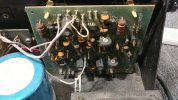
the underside of the citation 16 plus some corrosion.

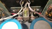
the usual amount of wiring and the business side of the large electrolytics.
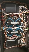
the 1000uf axial electrolytics hiding behind a fence of diodes might be a challenge to replace.

the negative screw seems to have accumulated some deposits that resemble oxidation. plus an up close look at one of the large diodes used in the system.
the usual amount of wiring and the business side of the large electrolytics.
the 1000uf axial electrolytics hiding behind a fence of diodes might be a challenge to replace.
the negative screw seems to have accumulated some deposits that resemble oxidation. plus an up close look at one of the large diodes used in the system.