• The move to the new server is done. There are some software and database maintenance updates in process. This has us passing the hat around to help out. We appreciate any donations. Seriously, even a dollar helps. The payment page may be found here - https://www.audiokarma.org/support.html

1060 rebuild on deck

klamsoss

Be willing to fail and try again.
Good afternoon AKers!
I've got a 1060 on deck for a rebuild. It hasn't been powered up in a couple years and the glue on the boards has corroded most of the caps pretty well. Nothing has been touched in the power supply since it was manufactured, so it's long overdue for some attention. I've ordered a few parts, but I wanted to get a central thread going where I can AK-source info to guide my work and finish up my BOM for the rebuild. My plan is to replace anything that is out of spec, and make some targeted upgrades where they may significantly improve reliability and/or performance. Reliability is top priority.
I'm comfortable working in tubed components (Fisher X-100-B and FM-100-B, Eico ST70, and I have a tube signal generator and VTVM I've restored) but I have done literally nothing in the way of servicing solid state equipment beyond changing fuses. So, be gentle, and details are much appreciated.

To start with, I intend to replace every electrolytic, since so many are visibly degraded, and they're all past their intended design life, anyway. I've been reviewing threads on rebuilds (lots of them! a good model with which to jump into solid state!) and there seem to be two camps:
stick with stock values,
or,
JACK 'EM UP!!
I'm hoping that AKers who have actually rebuilt, or own a rebuilt 1060 can weigh in on the merits of one or the other route. I'm guessing that I'll end up in a middle ground where I'll increase capacitance for some positions, and leave it stock for others but I'm open to all options. Please note, however, that this isn't a cost-no-object restoration. I'm willing to spend a bit, but I burn most of my bread on my bike collection and my tube stuff.

I'm also wondering about replacing a lot of these smaller value electrolytics with film caps that should last until my great-grandkids are using this to blast The Clash in their underground geodesic living spheres and wondering if "London is burning" is a reference to the war with the machines. (Just kidding. They'll be using my Fisher and Eico amps because transistors won't live through the EMP that wipes out the machines).

diodes?
known problematic resistors or other parts?
recommended improvements to the circuits?

So, experienced 1060 owners and restoration experts, what say you?
Many thanks!
 
Register to hide this ad
I mostly have worked on receivers, so can't be much help on the particulars of the 1060. But in general, for these solid state units, work on one board at a time and then test. And always power through a Dim Bulb Tester when powering up after making any change. It can save your bacon if there is a short somewhere.
 
I mostly have worked on receivers, so can't be much help on the particulars of the 1060. But in general, for these solid state units, work on one board at a time and then test. And always power through a Dim Bulb Tester when powering up after making any change. It can save your bacon if there is a short somewhere.
Thanks Steven. I guess I should say that I have a pretty full setup:
In addition to the vacuum tube signal generator and voltmeter, I also have 4 DMMs, my staco variac runs to a DIY monitor panel - analog gauges for 0-150 VAC and 0-3 amps AC (I need to rebuild it with a fuse for the ammeter, and possibly add a switch and a 0-15A meter for higher draw devices), a tektronix 465b oscilloscope, and a heathkit frequency counter. I haven't found the dim bulb tester to be necessary because the ammeter gives me info about the current, but again, I've only been doing this for about a year, so if there are merits to the dim bulb beyond gaining info about if there is excessive current, I'm all ears!
 
Stick with the same values, except for the three big caps. I've done three 1060's.
what do you recommend for the big caps?
And can you weigh in on the performance/reliability improvements gained by bumping the capacitance up?
 
Thanks Steven. I guess I should say that I have a pretty full setup:
In addition to the vacuum tube signal generator and voltmeter, I also have 4 DMMs, my staco variac runs to a DIY monitor panel - analog gauges for 0-150 VAC and 0-3 amps AC (I need to rebuild it with a fuse for the ammeter, and possibly add a switch and a 0-15A meter for higher draw devices), a tektronix 465b oscilloscope, and a heathkit frequency counter. I haven't found the dim bulb tester to be necessary because the ammeter gives me info about the current, but again, I've only been doing this for about a year, so if there are merits to the dim bulb beyond gaining info about if there is excessive current, I'm all ears!
I am no expert, but I have seen discussions of Variac vs. DBT on several threads. From what I have gleaned the Variac is great for tube units, but does not give the instant over current protection that a DBT does, which is helpful in the solid state world. Some people use both. But the DBT not only gives you instant feedback, it is protecting from over current at the same time. The Variac doesn't do that.
 
Use a dim bulb. No variac. The dim-bulb is a safety belt. It’s amazing.

Stick with the same values on the caps, except the main caps. The big one gets replaced with a smaller cap—get a new mount for it. There are holes already there for a 1 3/8” clamp.

Redo the small transistors all over as well, along with the power supply diodes. There may be a pair of glass bead diodes on the amp board that get replaced too.
 
Thx eastpoint. Once I get into it (probably this weekend) I'll be coming back for suggestions on specific replacement parts as far as diodes and transistors go.
 
I've got two 1060's, one is all original and just yesterday I hooked it up again from storage. It still sounds superb.
The other was my first recap, It got Silmic ii pretty much throughout with the exception of an epcos 10000uf main and Nichicon KG 6800 coupling caps.
Lessons learned were that I wasn't big on film caps, going back to silmic harmonized better. I say stick to the original output caps size which is about 3300uf, I'm in the process of do this myself.
If recapping is you destination then go for it, I have a bit of gear now and some of it I wont touch just yet, I have a nice Peak ESR meter that reads the condition of the caps, most caps read ok in ESR but drift a little in uF. They can still sound fine with slightly aged caps, yes a recap can bring the things back to spec but it can be a challenging task getting it to sound the way you like it, at least that's what I've found in this hobby over the last 5 years.
People say caps don't change the sound, well they do, just the same as cream bun from one shop isn't going to taste the same as one from another, you will have a favorite. Here's a shot of mine, with Russian oil caps in the pre-amp. Good luck!

20200213_114506.jpg
 
@AnalogueBen thanks for the input. Sounds like your experience (and RJ's) is similar to my own. I noticed subtle but clear changes in sound character when I put russian PIO caps in my Fisher, especially after they burned in a bit. I enjoy the sound character more with the K40/42Y PIOs than I did with the Panasonic films that were previously in there. But, my dad prefers the panasonics. Everyone's ears are different.
The key is knowing what you like, and matching up your parts and components to get it.
For this project, I'm not necessarily worried about trying to mellow the sound out or sharpen it up by tweaking caps. Honestly, I don't even have a feel for the current sound so can't be sure what I'd tweak. Right now the plan is to do a good restoration, for function/reliability and include broadly accepted improvements. The thought being that I can come back in a year or two and change a few things once I have a feel for the character of the sound.

So, as for parts, are a 10,000uF main and the 6800uF coupling caps the consensus route if I'm going to be spending for big caps, anyway?

Also, EastPoint (or anyone else, for that matter), can you recommend replacement transistor part numbers (I usually go to digikey)?
I have a handful of UF5408 3A 1kV diodes leftover from work on a tube amp. Would those be appropriate in the Marantz or better to use another part?
Also have CL80 and CL90 thermistors I could use to resolve any potential current inrush issues, if that's a wise choice for long-term reliability.

This is all kinda different for me since I'm used to working on massively higher voltages in tube equipment. Coupling caps in my Fisher are 500V and even the main power supply is 250V!
 
Most people are happy with a 10K and I think it's the limit of what the stock bridge rectifier will cope with, then you also have the power switch to consider which a safety cap may reduce that somewhat if I understand correctly. On the output coupling caps, I have reads a heap of posts on upping the uF size, and it's low end benefits, but found better reason and others own accounts to leave them standard sizing. They are in the signal path and like other coupling/de-coupling areas we are advised not to alter those positions, so that's my take. Besides the 1060 has 3300uf's as stock and makes enough bass for its 30WPC size IMO.
Can't quite say for certain about your diodes, but likely they could, try a search here using the part number or even just ask around.
 
...I have a handful of UF5408 3A 1kV diodes leftover from work on a tube amp. Would those be appropriate in the Marantz or better to use another part?...

For the P800 board? The UF5408s are quite a bit bigger than the stock diodes; the UF40xx series could be used.

Also have CL80 and CL90 thermistors I could use to resolve any potential current inrush issues, if that's a wise choice for long-term reliability...

Thermistors on primary are not recommended for solid state class AB amplifiers; they are fine for class A and tube amps where the current draw is more or less constant. See this thread for further details: https://audiokarma.org/forums/index.php?threads/ntc-thermistor-for-inrush-current.298575/
 
I've had a couple 1060's for about 12 years now. I used one regularly until about 7 years ago, and they've been in storage until recently. About a month ago, I finished up with the first one. I replaced the main caps and caps, a couple diodes, and a transistor on the power supply board. After cleaning all switches and pots, it sounded great, but I wanted to be able to use it without worrying so much about it. At some point, I'll replace caps on the amp board. As for the other boards, this amp sounds so good that I'll likely leave them alone.
My second 1060 is a much earlier serial number unit with the engraved faceplate, but it's not quite as good cosmetically, and it has a horrible hum (unlike the first one), so it definitely needs some love. I will say that a 1060 is the perfect model to learn on; it's easy to work on, very well documented, and simple. I believe I listed the components I used in another thread... I'll have to look for it.
 
I used 6800 uf 80v caps to replace all three. I buy them in bulk and use them whenever possible.

The transistors you’ll need are KSC1845, KSA992, KSA733, and KSC945. These will sub for everything except I think you need a KSC2383 for the power supply. The two power supply diodes can be 1N4005 or probably 1N4004. Don’t use the 5408s—those are way overkill and the wires are probably too thick.

I use Nichicon PW and KT caps for most of it, Panasonic FC for the power supply (PW would be fine though), and a lot of Wima film caps too.

I always replace the power switch, snubber cap, and knob too.
 
I swapped out the transistors on my pre board during the recap, using ksc1845 and ksa992. It wasn't until I put the original's back in that the amp sounded like it should. Now I replace only when failed.
 
Okay, update on the project!
First of all, HOLY (expletive) are these things easier to work on that point to point tube amps with nothing labeled and nothing obvious! I replaced every small electrolytic cap, and a few mylar, and ceramic caps, in a total of about 3 hours of work. And I'm not a pro... sheesh!

Anyway.
Started by cleaning every contact point with deoxit. Lubed switches and pots with MG chemicals 'contact cleaner with silicone'. Its what my local guy had. Seems to do the job.

Next up was all the small electrolytics. Still waiting to place an order for the big coupling and power supply capacitors because I want to determine if I'm going to change out any transistors and I now have a 2230B coming in the queue. I didn't go with audio-specific caps because I have a bunch of nichicon on hand, and I like to support my local electronics shop guy, and that's what he sells. I may ask him to get me the gold nichicons in the future, but I used what I had for this one. In some cases, I replaced larger value ceramic caps (2200pf+) with films, and smaller value electrolytics (1uf and smaller) with films, especially in the tone control and preamp boards. My work on tube integrated amps has led me to the conclusion that these are the "heavy hitter" areas for sound quality, and the best bang for the buck when it comes to using "the good stuff".
I also bypassed electrolytics in a couple other specific areas with 680pf poly film caps. I use that trick on crossovers in speakers with great success. I figured it couldn't hurt inside the amp. In the pics you will see the bypass caps are little red jobs, real small.

I'm going with 3300uf couplers, and 6800uf nichicon gold for the main supply. A fairly modest bump on both accounts. Nothing to worry about in terms of inrush current (or so I believe). They'll be in next week. Then this puppy will be burned in for a bit and off to Montgomery, NY where my sister will use it in place of her own 1060, which will come back to me for the DELUXE treatment. Russian military and nichigold caps throughout, new binding posts, and I'm going to internally wire their bluetooth reciever.

A few things I ran into:
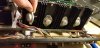
*The phono board looks like it has 4 of the same mylar caps on it. According to the service manual, one pair are supposed to be .47uF (c917, c918) and the other are supposed to be 4700pF(c911, c912)... they look identical, so I'm wondering if there is an error in the construction or the schematic. Can anyone help me with that?

What is this "safety cap"? In my tube amps, the safety cap (aka "death cap", ironically) was the cathode supply cap and had nothing to do with the power switch.... what am I looking for here?

Last thing:
What are peoples' takes on the transistors. So far I've had 2 folks weigh in and say, basically, "change em" and also "don't change em".... so I want to hear a bit more about why or why not. Hopefully others can weigh in.

Photos:
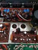
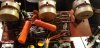
1. Before any work was done.
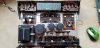
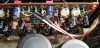
2. "Before" - preamp board.
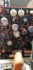
3. "Before" - phono board
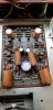
4. Phono board after.*
5. Tone control after. Note 2200pf orange drops and 1uf Dayton audio films
6. Main amp board after. Note red bypass caps
 

Attachments

  • 20200216_154418.jpg
    20200216_154418.jpg
    76.1 KB · Views: 99
  • 20200216_154532.jpg
    20200216_154532.jpg
    39.1 KB · Views: 94
  • 20200216_154502.jpg
    20200216_154502.jpg
    44.7 KB · Views: 93
  • 20200221_173202.jpg
    20200221_173202.jpg
    47.5 KB · Views: 92
  • 20200217_204542.jpg
    20200217_204542.jpg
    62.2 KB · Views: 94
  • 20200221_173227.jpg
    20200221_173227.jpg
    76.7 KB · Views: 98
The only transistors that weren't bad that I replaced in my two were the 458's Marantz used in some of the preamp and phono boards. The KSC1485 works well as a replacement. That's what I used. The 1030 I restored had 6 or 8 of the 458's, some on both boards. The 1060 only has a few. These can go noisy. I had a couple that introduced a hissing sound. I just replace all I come across. The KSC1845's are cheap. I keep a supply of them. I tried several different film caps in place of the original "fat browns",
And wound up putting them back in. I liked how they sounded.
 
Output transistors were removed, cleaned with rubbing alcohol, and a fresh treatment of silicone paste was applied. New coupling caps are fully wired in (2 sided foam tape) and the power cap is in place but not wired. I kept the power cap at 4700uF. Couplers are nichicon gold and the power cap is another of nichicon's audio specific caps. Normally I hand match my caps to 0.1% (or as close as I can get) but none of my meters will test caps this big, so I'm not sure if they're perfectly matched. I also opted for the caps based on the production series and values rather than size, so they obviously don't fit the original clamps. Not the prettiest but don't plan to have this open much.

I have the diodes I need to finish off the power supply board, and the small transistors for the phono board, and I have an appropriately rated cap for the snubber. Is the snubbed located on the actual power button assembly? Or closer to where the AC cord comes into the chassis?

I'm also modifying my "AC line stack"... it's my homemade power monitoring box. Right now It includes an AC voltage meter, and ammeter up to 3A. And a wall socket. I'll add a swit h, dim bulb, 10A meter and put fuses in line before both meters to keep them from being blown out.

If I understand this right, I would want the dim bulb wired in series BEFORE the ammeter on the 10A circuit, right? Otherwise I'd be measuring current used by the bulb itself, too.
 

Attachments

  • 20200301_010424.jpg
    20200301_010424.jpg
    65.2 KB · Views: 66
  • 20200301_010428.jpg
    20200301_010428.jpg
    51.3 KB · Views: 64
Last edited:
I had been under the impression that audio specific caps generally all have low equivalent series resistance. Do they not? Since the power supply cap has not been soldered in, it's nothing to use a different part.

As for the AC stack, I will post a thread in the DIY section when it's done. But basically it's just for testing, and correct, it will do nothing to AC quality, nor is it intended to.
For testing purposes I typically plug it into the variac and bring the voltage up while monitoring current. Also allows me to keep an eye on line voltage during tests. My house line drifts. *remember, folks, if your wall voltage drifts, your variac drifts too, unless you have a separate conditioner or other line de-crapper* Handy for monitoring without tying up multimeters, and I spent all of $40 building it($9 of that was for the celebratory post-build 6pack). The existing arrangement works great for my tube gear but I think solid state stuff draws over 3 amps under some test conditions. That, and my limited bench space, is why I'm planning to add a switchable 10A metered plug, with the dim bulb in series. Idea being an all-in-one device, less real-estate on the test bench...
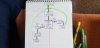
I've attached a quick sketch of the planned wiring for the stack. The yellow is neutral (white wire), thick black marker is hot (black wire), and good old green ground. Fuses are indicated with an X on the hot wire. Anyone see issues here? Still think it better to do a basic dim bulb separately?

Side note:
If not in use for testing, I keep the stack plugged into the wall to provide at-a-glance wall voltage reference on my wildly variable house line (114-124.5 VAC, though it's 118-121 VAC range probably 75-80% of the time). A convenient reminder to adjust the bias on my tube gear if the wall voltage dips or rises outside of the usual range.
 

Attachments

  • 20200301_140425.jpg
    20200301_140425.jpg
    47.8 KB · Views: 34
Last edited:
So, I'm pretty sure this blue guy is the snubber, but it doesn't match the 0.033uF on the schematic, and I don't understand what the markings mean...
My first impression is that it's a 0.1uf cap in series with a 120ohm resistor, but that's not shown in the schematic, either.
I have 0.1, 0.022 or 0.047 (no 0.033) and 0.01uF at pretty much any voltage on hand, but I want to make sure I understand what I'm doing here...
 

Attachments

  • 20200301_151215.jpg
    20200301_151215.jpg
    43.2 KB · Views: 56
Last edited:
Back
Top Bottom