• The move to the new server is done. There are some software and database maintenance updates in process. This has us passing the hat around to help out. We appreciate any donations. Seriously, even a dollar helps. The payment page may be found here - https://www.audiokarma.org/support.html

1060 rebuild on deck

Thanks Mr. dog!
It looks like I need to get one of these special snubber caps, and that my standard films won't do the job here, even with a resistor in series.

Okay, I'll order a handful (since I'm doing at least one other 1060, and a 2330B, with more to come, almost certainly).

Now I'm trying to figure out if the pins on the 1845 transistors I got are the same pattern as the pins on the 458 that they will be replacing.
 
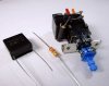
The QuenchArc snubbers are pricey. I use them partly for the quality and mostly because they are easier to install than making one. You can use a 0.1uF/300V film capacitor, and a120ohm 1/2 watt resistor, in series. Total cost is less than a dollar, exclusive of shipping.

Here's a picture of the parts, and installed on a switch:
IMG_0150_resize.JPG
 
Ahhh okay, cool. I have all that on hand, so I whipped one up. Just got the pinout sorted for the 458 replacements. Now, just a few diodes on the power board, wire up the filter cap (switched to a 6800uF lower ESR based on prior discussion. I had it on hand, so no sweat) and after that, I think I'll be on to finishing up that dim bulb tester modification of my AC line stack (I call it a stack because the meters are all stacked). I'll be ready to test it out and start the process of setting everything to factory spec. That'll probably be a later-this-week process.

Super excited to hear what this thing sounds like after having it refreshed. It'll be a nice backup for the Fisher!

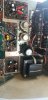
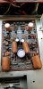
Pics:
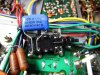
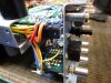
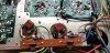
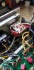
1uF films bypassing the output caps
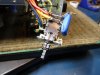
New DIY snubber.
 

Attachments

  • 20200301_170424.jpg
    20200301_170424.jpg
    76.3 KB · Views: 62
  • 20200301_170412.jpg
    20200301_170412.jpg
    42.5 KB · Views: 60
Last edited:
My understanding is that the snubbers are made with safety caps (plus resistor), meaning that if they fail, they fail open rather than with a short. I use the dedicated snubbers for that reason.
 
Steven, wouldn't a 1/2w resistor tend to fail open if it were to fail?

If not, I guess it might make sense to use the real deal...

Definitely will be getting a few for units that aren't mine. I wouldn't want a restoration I do to be faulty.
 
Steven, wouldn't a 1/2w resistor tend to fail open if it were to fail?

If not, I guess it might make sense to use the real deal...

Definitely will be getting a few for units that aren't mine. I wouldn't want a restoration I do to be faulty.
I’m no expert in these things. I’ve just seen this in AK discussions over time. I figure if it was the original type, I would try to keep it that way. Good luck with the restoration!
 
@Steven Tate do you still have that 2325 I've seen you talk about on a few threads?
I have one of those in the queue now, too. Would love to pick your brain about it in a month or two when it makes it's way onto the bench.

ALSO
I should have some time tonight to spend on the 1060. Going to recheck that I used correct polarity on all the caps I replaced, then DBT it and see if anything blows up.
 
@Steven Tate do you still have that 2325 I've seen you talk about on a few threads?
I have one of those in the queue now, too. Would love to pick your brain about it in a month or two when it makes it's way onto the bench.

ALSO
I should have some time tonight to spend on the 1060. Going to recheck that I used correct polarity on all the caps I replaced, then DBT it and see if anything blows up.
I still have it and it’s open on the bench. I turned it on and got big distortion. Took it to bench and hooked to test speakers and it sounded perfect. Went back to listening room and remembered I bought some new speaker cables a while back. They had metal ends that slipped into speaker outputs. I didn’t realize that the outer cases were hot, and they undoubtedly were touching. I’m lucky I didn’t blow some outputs or more. Anyway, it’s fine except for the sizzle. While it’s on the bench, I’m at least going to separate the Pre from the main and see if it still sizzles. Who knows - I might decide to chase it down. But for my own use, it doesn’t really bother me.
 
Okay, I checked everything over and once I was satisfied, I plugged it in and pressed the power button, fingers crossed.

There was a split second current spike and then less than 0.2 A at idle. So, that much is good.

I then set about the "power amplifier adjustmens" process.
First question: the service manual says use a VTVM to set the trimming resistors. My VTVM doesn't go down to 7.5mV, at least not accurately. So can I just use my handheld fluke dmm?

So, I set the voltage across R747 to 7.5mV on my DMM and powered off. I then moved my probes over to R748 and prepared to set the trimmer for that side. I powered on and wasn't getting good contact with the mini-grabber probes. While adjusting the probes so I could get a stable reading, I got a SNAP from somewhere in the vicinity of the p700 main amp board. I couldn't tell where because of how I had the amp positioned. I immediately powered it off. No smoke, no visibly blown resistors. I've made the mistake of reversing polarity on a cap and the snap sounded like it could have been one of the small electrolytics. Nothing visibly damaged or bulging, and I saw no evidence of any sudden current spike...

What do you guys think? Maybe just some errant dog hair that shorted something just long enough to make a snap? Maybe some flux that dripped?

I'm kinda afraid to power back up for fear of doing damage.
 
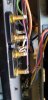
Went ahead and implemented the same 5-way binding post addition that many others have used on this amp. Since this will be a backup/utility amp that will probably move a fair amount and be connected and disconnected frequently, this is really going to make life easier.

Also used the original clamp to mount the main power filter cap. I wasn't satisfied with how secure the double sided foam tape was. I used an old bicycle inner tube wrapped around the cap as a spacer.

After all that was done, I did some mapping and found better, more reliable connection points, along the strip of "J" labeled solder posts, for the power amplifier adjustment tests.
I powered up again. No drama for at least the first 90 seconds, which was all it took to get the first set of trimmers pretty close. Just as I got them in line I noticed a really faint clicking. Looked around quickly to see if I could tell where it was coming from, but I did not before I noticed I hadn't satisfactorily soldered the safety cap on the power switch. Good mechanical contact but solder hadn't flowed well at all. Dunno how I missed that before. Any ideas on the clicking?
Sounded like tiny bubbles popping. Maybe flux getting hot? Maybe an electrolytic cap boiling internally? Maybe I just need to let it idle for 5 or 10 minutes and see if anything blows?

So, another process question:
What's the quickest and easiest way to discharge all the caps in a solid state unit?
For my tube stuff, I have only 5 or 6 caps over 2uF so it's quick and easy. In this bad boy, there are the big dogs(filter, coupling), but then also a dozen or so smaller ones. Should I just discharge the filter and coupling caps and call it good?
And how low do I need to drop the DC voltage? It takes a while for these to discharge through my DIY 20k 5watt discharge tool.
 

Attachments

  • 20200308_144322.jpg
    20200308_144322.jpg
    35.8 KB · Views: 58
  • 20200308_144334.jpg
    20200308_144334.jpg
    54 KB · Views: 56
  • 20200308_151323.jpg
    20200308_151323.jpg
    47 KB · Views: 55
Well, turned it back on to see how things wentAfter 3 minutes, I found smoke coming from c919 on the phono board. So it WAS the sound of a cap boiling internally!
I have the cap oriented the proper way based on the markings on the board, but the schematic shows it the opposite.
AND...

This is why you take pics BEFORE you rip stuff apart. My pre-resto photo shows that the board is marked wrong. You can see in the first pic, the purple elna is clearly opposite orientation.
2nd pic is the exploded one. Looks like my belt after a big meal...

Glad nothing more than that!
 

Attachments

  • 20200216_154502.jpg
    20200216_154502.jpg
    44.7 KB · Views: 65
  • 20200308_155200.jpg
    20200308_155200.jpg
    55.6 KB · Views: 65
Last edited:
I don't have a distortion analyzer so I can't do all the performance checks in the service manual. I did adjust the trimmers to make the clipping equal, though, and checked the DC offset. The readings aren't stabilizing. They jump around between -50 and +50 mV, though mostly positive, and mostly less than 30mV. Is unstable dc offset typical for these? Indicative of another issue?

It looks like I have some channel imbalance on the 'scope. Seems mildly inconsistent through the volume range, though, so I'm thinking it might just be the volume pot, which I can live with since this thing has a balance control. The right side always puts out more voltage, but the difference is variable. I suspect this is related to the dropped left channel mentioned below:idea:

Okay... so I did the above testing, the scope never displayed a dead channel, but...... after trying it out with some music, it sounds quite good for 2 minutes on startup, but then about 3 minutes later, presumably when it is up to operating temp, the left channel cuts out. If I press the right mono switch, left comes back, and she'll put out sound longer with all the covers off. Something in some part of the preamp? No idea what it would be though.
Not sure if it happens with inputs other than aux1.

Obviously I need to solve this dropping channel issue, but, are there other tests that Marantz fans recommend that don't involve a distortion analyzer? I need to get to my next project, a 2325B, for which I am being paid in records:banana: but I won't shortcut this one. I want it to be as perfect as practicable given my available equipment.
 
Last edited:
Who likes a good mystery?

Observe:
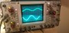
picture 1 is the scope output from a 1kHz signal fed from my gen into the aux input on BOTH sides.
Scales are equal. Clearly the channels are out of phase, and one is at half amplitude. Makes no sense...

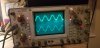
Picture 2 is the same situation, with the R Mono switch depressed. Near identical amplitude, but still out of phase. :eek:

AND:
I have spare separates... I plug the 1060 preamp out into separate power amp (a b&k with 140wpc), works fine on both channels, but has to be turned up pretty damn far to get it loud (over 75% vol on the marantz... seems odd with 140wpc).
I switch to run my MF E20 preamp into the "main in" jacks on the marantz, and both channels work, but again, I have to turn it up pretty damn high to make it remotely loud.

For reference, when I plug the MF into the b&k, i cannot go past 25% volume in my room. Maybe in a bigger room, but this combo is so strong it's borderline unusable.

Okay, I know you're thinking "it's the jumpers between the pre/main jacks, dummy! How was that not the first check?!?!?!"
Fair... that would have been the easy first check.

Well, it's not the jumpers. I tried 3 sets of known good cables, same result every time. :dunno:

What do you guys think?
 

Attachments

  • 20200310_224446.jpg
    20200310_224446.jpg
    58.2 KB · Views: 14
  • 20200310_230031.jpg
    20200310_230031.jpg
    54.8 KB · Views: 14
CH1 or Ch 2 invert pressed, trigger problems on scope?
I see the uncal lights are on.

I sometimes have to do an o'scope sanity check using a known good unit.

Tom
 
CH1 or Ch 2 invert pressed, trigger problems on scope?
I see the uncal lights are on.

I sometimes have to do an o'scope sanity check using a known good unit.

Tom
I'm not using any triggering (I think?) and I did check the invert switch, which is NOT depressed in these shots. As for the uncal lights, I think those are related to the VAR knobs not being off. BUT, I should check that. good tip. And, to be honest, I really know almost nothing about using an oscilloscope beyond how to hook it up and adjust the ranges so I can visualize waveforms. I'm rather new to this sort of stuff, but learning rapidly.
I can use a in and out of phase test tracks on a known good amp to see if my scope setup is wrong. That's a good tip... hadn't thought about my setup being bad.
 
The uncal thing on my oscilloscope was just due to the variation knobs. Switched those off and verified waveforms on my scope with some signals straight from the source. Looks like I have it set up properly. Good sanity check, though.

So, after that, I fussed around with the 1060 a bunch. I replaced a few additional 2sc1000 transistors, not because they were bad, but because I thought there might be a cold-solder somewhere (there wasn't). Then I hooked up to the oscilloscope, but I couldn't get anything that seemed right to show up on the 'scope. In fact, I wasn't getting any signal at all, anywhere. Not at the preamp out jacks, not at the speaker terminals. Nowhere, despite being sure that the scope was working properly and the signal generator was working properly. Annoyed, I was going to pack it in for the night but figured "what the heck... let's just see what happens if I hook up speakers".

Lo and behold... sound, in both channels! Equal at all volumes!
I have no idea what fixed the issue, or why I couldn't trace it with the scope.
Anyway, I set the trimmers 730 and 729 for the appropriate 7.5mV (do these things drift normally? They don't settle in well for me.. .+/- 0.2mV drifting back and forth) and buttoned it up temporarily to see if it would drop the left channel after it ran for a while. I gave it a few hours of "burn-in", during which sound quality went from "not very good", according to my notes, to "hmm, now THAT'S more LIKE it." It didn't drop either channel or do anything uncivilized.
I still need to look at the waveform to adjust the clipping trimmers, but to do that I'll have to get a waveform from the speaker output on my scope. Hopefully whatever miraculous affect resolved the channel drop issue will allow my scope to get some good waveforms next time I have a chance to work on this.
 
Back
Top Bottom