Just on Left, Right sounds greatWhen you play music, do you still hear a distorted sound? On L, R or both channels?


Just on Left, Right sounds greatWhen you play music, do you still hear a distorted sound? On L, R or both channels?

I switched the connector on JE04 and the distortion is now on the right sideLet's see if we can locate where the L channel signal goes bad. Maybe we can do this:
- I want to swap L & R channels on one of the connectors where there are only 3 pins: L, R, Gnd
- Maybe we can start at JE04 on the PE00 Pre/Tone Amp board. This is before the Volume control.
- Can that connector be turned 180 deg and plugged in? That would swap the L & R channels.
- If we can do this, and if the L distorted channel changes sides, then we know the problem is before this connector
- If it remains on the same side, then we try the next connector.
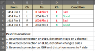
I reversed the connector on J414, distortion stayed on left.. I know i wasnt asked but I reversed the connector on JE02 . distortion changed sidesGood. That means that the distortion is introduced before this connector and the PE00 board.
Put the JE04 back to its original orientation and let's move back a step.
Can you get to J414 on the P400 board and turn it 180 degrees and see which channel has the distortion?
I reversed the connector on J414, distortion stayed on left.

I cleaned the slider but no luck, I will work on it again tomorrow afternoon, can you let me know how i jump itView attachment 3817532
- Distortion stays on the L channel at J414 means that both L & R signals coming out of J414 are good and the problem is after the signal leaves J414.
- Shielding on the wire ties either a foil, braided wire, or a single conductor wire to ground to prevent noise from either entering or leaving the other two signals.
- The signal goes from J414 (good), through the balance control, then into PE00 JE04.
- The distortion has to be introduced somewhere along this path.
- I forget, did we have an issue with the balance control before?
- Try to clean it with some Deoxit and see if the distortion clears, otherwise we can try to jumper around the balance control and see if the distortion goes away.


J414 pin 1 direct to JE04 pin 3 = goodThat's good! This also (I think) says that the Balance control is NOT the problem.
So, J414 Pin 1(L) connected directly to JE04 Pin 1(L) has distortion.
For completeness, we will try the other 3 cases:
- J414 Pin 1(L) connected directly to JE04 Pin 1(L) = has distortion
- J414 Pin 1(L) connected directly to JE04 Pin 3(R) = ?
- J414 Pin 3(R) connected directly to JE04 Pin 1(L) = ?
- J141 Pin 3(R) connected directly to JE04 Pin 3(R) = ?
Unfortunately JE07 connection is 3 pins and JT01 is a black connector the pins slide into, we cannot reverse thatGood morning. Here is what we know so far.
View attachment 3817730
Now let's see if the PT00 Filter Amp is causing the problem on the L channel.
Is there a wire connector on JE07 or JT01 (PT00 Filter Amp) that you can rotate 180 deg?
Ive already done that earlier, when on Aux or Tape 1 i get a large wave on pin 1 and Pin 3 on JEo7 they are both very steady and clear...You just need to be able to get your scope probe on pin 1 or pin 3 of JE07 to look at the sine wave that you are inputting into the Aux or Tape In. It doesn't need to be on the connector itself. If it's easier you can clip the probe on CE13 (L) or CE14 (R).
Are you able to do that.
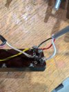
I tested JT03 Pin 7 and Pin 9 , the wave on both where clear, the same and higher than anywhere else i tested. While testing i finally know why right channel sometimes lowers volume. the connection on the slider on the right that has the Yellow wire as per photo has an issue, i think inside. if i wiggle it i can loose sound , pushing it to one side gives perfect right volume.What about JT03 Pin 7 (L) and Pin 9 (R)?
Is the wires that go to JE02 the wires that go to pre out?The signal comes into the board on pins 7 & 9, goes through the volume control then out JE05 to the Preamp outputs.
If the signal looks good on pin 7 and 9, then the distortion must be coming from the volume control, board traces, or wiring to the Preouts.
Yes, the go to the Preout RCA jacks.Is the wires that go to JE02 the wires that go to pre out?
Ill test the connection from JE02 on all three wires to the pre outsYes, the go to the Preout RCA jacks.