So i need to correct myself
L005 works
LN01 not engaging
LC01 cant tell it looks like a chip on the power board
Last edited:


So i need to correct myself
Sorry correct ,it looks like a chip i can see it but im not sure how to test if it is working. I know LN01 is not working , I can see and hear the L005 works
Got the unit out of protection mode.L005 looks like it connects to LN01 so I'm not sure what is going on.


Not any i replaced.Wow!
I found these errors listed while looking on the internet.
Do any of these apply to you if you changed any components?
Service Manual Errors Notated:
- P850 PSC - C853 1000uf 25V ***printing on pCB polarity is opposite what should be
- PT00 Filter Amp - CT23/24 47uf 16V CT24 opposite PCB polarity
- PQ00 Soft Start - CQ05 33uf 35V (manual says 22uf 35V)
- P700 AMP - C709/710 .47uf 50V NOT PRESENT ON EURO
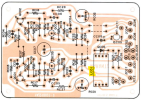
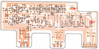
JT04 should connect to two pins on switch ST01-4 as shown with the red arrows.There is a wire JT04 that goes to the PT board, it is connected but does not have continuity to the pin the trace goes to.
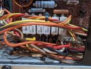
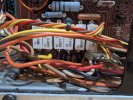
If you are referring to the resistor leads that have a loop on them, you can measure the voltage with respect to ground and as far as I can tell they should be close to 0v.can i test voltage at the resistors shown in the photo from the two tabs shown at the bottom center,
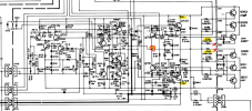
R729 and R730 are used to adjust the DC Offset to 0v at the speaker terminals.are they affected by R729 for the first amp and R730 for the second
Are you asking what voltage you are looking for when you adjust R729/R730? If yes, read below.Lastly if i am correct what voltage am i looking for.

This is the second time i leave the unit for a day and protection relay does not engage. and unit plays again.JT04 should connect to two pins on switch ST01-4 as shown with the red arrows.
View attachment 3820644
If you are referring to the resistor leads that have a loop on them, you can measure the voltage with respect to ground and as far as I can tell they should be close to 0v.
View attachment 3820647
R729 and R730 are used to adjust the DC Offset to 0v at the speaker terminals.
Are you asking what voltage you are looking for when you adjust R729/R730? If yes, read below.
If you are asking about some other voltage, please be more specific.
View attachment 3820660
Multimeter set to mlvt, black probe to chassis , red probe to either tab at bottom of row of resistors,Those readings should be closer to 0V. Did you try to adjust R729 and the one on the other channel?
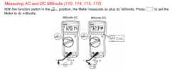
Fluke 115What make and model DMM did you have... I forget?
I set it as directed, speakers disconnected, nothing connected to any source, same outcome on first amp maybe left, but was able to set second amp to floating 0For the Fluke 115, you need to:
View attachment 3820895
- Black lead to COM, Red lead to V
- Function dial set to mV
- Press yellow button to select DC mV
- The display should show "mV" and "DC"
View attachment 3820904
Yes volume off, selector at AUXSelector set to AUX. Volume control fully counter-clockwise?