• The move to the new server is done. There are some software and database maintenance updates in process. This has us passing the hat around to help out. We appreciate any donations. Seriously, even a dollar helps. The payment page may be found here - https://www.audiokarma.org/support.html

2385 reconnect PS00 to P400 pin question

What exactly are you trying to do? Are you trying to set the DC offset?
If you are measuring DC Offset, and adjusting R729, then you need to attach your DMM to measure mV across the speaker terminals and adjust to 0v.
Is that what you did?
When starting up the receiver the speaker relay LN01 is not engaging. Maybe i have bad info but i was told if it is not engaging you cannot measure mv at speaker terminals but you can at the resistors on each amp.
I set my meter on MV, DC Black probe chassis, Red probe one side of R786, using trimmer R730 set to 0mv
Black probe chassis, Red probe on one side of R785, using trimmer no affect MV floats from 135 to 59 up and down
 
Last edited:
Ok both amps set at 0 to 0.2 mv
Still relay does not engage
What else would keep the relay from engaging?
 
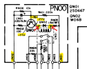
Check the voltages on the PN00 board (yellow highlights and red arrows).
View attachment 3821549
JN02=83vdc
JN01=0
QN01= C=72vdc B=75vdc E=77vdc
RN05=75vdc
On a very interesting note, when i turned on the receiver , LN01 not engaged, while testing voltage at RN05, LN01 engaged, sound on Left and Right was clear
I turned off unit to move board to get at QN01, turned back on LN01 would not engage, with power on while testing the 3 legs of QN01 the relay engaged but now sound on left channel was distorted again.
Touching with the probe affected something,
 
A couple of questions:
  1. All of your measured voltages are positive, but the schematic shows negative voltages. Is the schematic wrong?
  2. Which side of resistor RN05 did you measure the 75v on, the side connected to JN01 or the relay LN01?
  3. When the sound started coming through clear, did you notice any changes in any of the voltages?
  4. I have in my notes that previously we did not have audio on JN05 (R channel).
  5. I forget, did you replace relay LN01 with a new relay or is it original?
Relay LN01 is a 48V relay so it would need to have about 48V across the coil terminals for it to activate. You didn't tell me which side or RN05 you measured the 75v. If it is the side connected to the relay, it won't activate the relay. If it is on the side that connects to JN01 then the relay will activate but resistor RN05 would need to drop about 30V across it to bring the relay voltage down to <48v.
1787233788072.png
1787233804852.png
 
Last edited:
Measurements with proper polarity
JN02= -82dc
JN01= -64 dc then 0 when L005 kicks in
RN02=-73dc
QN01 B=-75dc C= 0 E=-75 dc
RN05 both sides -64 dc at turning on, then 0 when L005 kicks in
I replaced LN01
At time of testing LN01 not engaging
 
Last edited:
RN05 both sides -64 dc at turning on, then 0 when L005 kicks in
What side goes to 0v when L005 turns on? Both sides or RN05 or only the side connected to JN01?
If I understood your measurement, both sides of RN05 go to 0v when L005 turns on. If that is true, then you have 75v across the relay coil which would probably burn it out since it is a 48v relay. Again, if this is true then maybe RN05 is bad and is 0 Ohms, not 1.5k. You can turn off power and measure the Ohms across RN05.
 
What side goes to 0v when L005 turns on? Both sides or RN05 or only the side connected to JN01?
If I understood your measurement, both sides of RN05 go to 0v when L005 turns on. If that is true, then you have 75v across the relay coil which would probably burn it out since it is a 48v relay. Again, if this is true then maybe RN05 is bad and is 0 Ohms, not 1.5k. You can turn off power and measure the Ohms across RN05.
The RN05 measure 1.2 k ohms
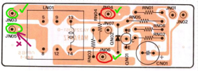
As in the photo when start up top side of RN05 no voltage, Bottom -64 dc, when L005 kicks in no voltage top or bottom
 

Attachments

  • PXL_20260820_152421760.jpg
    PXL_20260820_152421760.jpg
    129.4 KB · Views: 6
That means that the coil is not drawing any current or the transistor QN01 is not turning on since the collector is 0v (it was -74v before)?
Check the voltage across the coil (turquoise arrows). It should be 0v before the soft start relay turns on, then 48v after.
1787247680284.png
 
That means that the coil is not drawing any current or the transistor QN01 is not turning on since the collector is 0v (it was -74v before)?
Check the voltage across the coil (turquoise arrows). It should be 0v before the soft start relay turns on, then 48v after.
View attachment 3821796
Meter set for DC. Red probe on top turquoise arrow. Black probe on bottom turquoise arrow
O voltage before soft start, 0 voltage after
 
Check the QN01 EBC voltages again before and after the soft start relay click. I think before you measured the emitter voltage at about -77v, is it now 0v?
 
Check the QN01 EBC voltages again before and after the soft start relay click. I think before you measured the emitter voltage at about -77v, is it now 0v?
Check the QN01 EBC voltages again before and after the soft start relay click. I think before you measured the emitter voltage at about -77v, is it n
As luck would have it relay kicked in and voltages will not be the same as when its not.
Before relay engages= B=-75dc C=-64dc E=-75dc
After relay engages B=-82 C= -72 E=-72dc
 
Last edited:
Try to reflow the solder joints on QN01 to see if that helps to be more stable.
Reflowed solder on QN01. turned unit off and on 4 times relay kicked in, 5th time relay did not
I checked voltages on QN01 now that i dont have the relay kicking in
B=-82 dcv soft stat on or off C= -64vdc before soft start, 0vdc after it engages E no voltage before or after.
 
Well, either QN01 is bad or RN02 is bad. Power off, check resistance of RN02 = 100 Ohms and/or replace QN01.
Looks like voltage is coming in ton JN02 because QN01 base always has voltage, but QN01 emitter has 0v.
(By the way, when you say "no voltage" I don't know if you really mean 0V or unmeasurable voltage. Please be specific.)
 
Well, either QN01 is bad or RN02 is bad. Power off, check resistance of RN02 = 100 Ohms and/or replace QN01.
Looks like voltage is coming in ton JN02 because QN01 base always has voltage, but QN01 emitter has 0v.
(By the way, when you say "no voltage" I don't know if you really mean 0V or unmeasurable voltage. Please be specific.)
When I say 0 voltage I mean under 1vlt , do you know what replacement for the ,QN01
 
Back
Top Bottom