


You are using an out of date browser. It may not display this or other websites correctly.
You should upgrade or use an alternative browser.
You should upgrade or use an alternative browser.
2385 reconnect PS00 to P400 pin question
- Thread starter sendust
- Start date
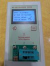
OK figured out why speaker relay would not engage, every time i would try and put the receiver back together the relay would stop engaging. if i removed the hold down screws and laid it flat it would eventually start working. I followed all traces with meter set on audible and found on CN01 negative side there is a trace that goes to RN06 and on the other side of the negative pin the trace goes to JN02. When i tested that trace i got intermittent connection. I exposed some of that trace and soldered small jumper wire.
The relay now engages and ive moved the board around then reinstalled the hold down screws. Still the relay engages so i have the issue solved/
Now i will put the unit back together to test areas you requested. .
The relay now engages and ive moved the board around then reinstalled the hold down screws. Still the relay engages so i have the issue solved/
Now i will put the unit back together to test areas you requested. .

Hi Dan, you wanted me to test QE03 and QE04 All voltage measurements DC
QE03 Pin 1= 12.58 Pin 2 =- 0 Pin 3 =- 0 Pin 4 = -13.78 Pin 5 = -12.45 Pin 6 = -0 Pin 7 = 13.25
QE04 Pin 1 = 12.47 Pin 2 = -0 Pin 3 = -0 Pin 4 = -13.78 Pin 5 = -12.40 Pin 6 = -0 Pin 7 = 13.1
QE03 Pin 1= 12.58 Pin 2 =- 0 Pin 3 =- 0 Pin 4 = -13.78 Pin 5 = -12.45 Pin 6 = -0 Pin 7 = 13.25
QE04 Pin 1 = 12.47 Pin 2 = -0 Pin 3 = -0 Pin 4 = -13.78 Pin 5 = -12.40 Pin 6 = -0 Pin 7 = 13.1
Kind of a pain but wow what a learning experience. Never on of these again ,too fragileWhat a saga! Reminds me of why I stopped taking on the 2385/2500/2600 units long ago.
Disclaimer: I'm not seeking any more stereo work on any model!

They look good.Hi Dan, you wanted me to test QE03 and QE04 All voltage measurements DC
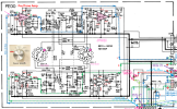
I noticed something while using the scope, while testing many points i decided to test J413, I saw nothing while testing pin 1 R But i notice a small tight wave while testing Pin 3 L. Not sure if thats anything but tried a few times and each time only wave of Pin 3.

So that can't affect left side except when using AM or FM?Before when I was tracing signals, I wrote down that J413 connected to the P200 - AM Tuner, FM IF, & MPX Decoder board.
View attachment 3823402
I made some RCA shorting plugs and installed them into phono 1, hum stayed the same, Increases with volume.
I removed the PS00 board and used two jumpers, with shorting RCAs out still hum but not as loud, connected RCA shorting cables and sound disappeared, only some at full volume.
I must still have issue with PS00.
I removed the PS00 board and used two jumpers, with shorting RCAs out still hum but not as loud, connected RCA shorting cables and sound disappeared, only some at full volume.
I must still have issue with PS00.
Hi Dan I feel i should recap my P400, PT00 and PE00 boards and step back and confirm all solder connections before moving forward.
I tied up enough of your time and want to make sure there are no other issues before trying find the distortion.
Seems every time i put the receiver back together there is some area that causes issues.
I tied up enough of your time and want to make sure there are no other issues before trying find the distortion.
Seems every time i put the receiver back together there is some area that causes issues.
Hi Dan, im finished re capping, also filed all pins with an ignition file and made sure all connections are good,
Same result, issue is not with connections or caps. I know we tested slider for left and right channel but i do have some kind of an issue.
Sometimes when turning on the unit, right channel would be missing, i would then touch the connector where the ground connects, or where the white connects and it will come back, I thought it was a bad connection, i removed all of the wires going to the slider, cleaned off all old solder and re stripped all wires before guiding them back into the holes of the pins and re soldered.
When i turned on unit same right channel missing and if you touch ground connector or volume stem you get a loud hum. I moved the connector with the ground wire on it and right channel came back and no hum when touching ground connector or volume Sometimes touching the connector with the white wire does the same thing issue must be inside the the slider. Not sure how to fix this. Could this be because I just re soldered to connectors without cleaning with alcohol or use paste
Same result, issue is not with connections or caps. I know we tested slider for left and right channel but i do have some kind of an issue.
Sometimes when turning on the unit, right channel would be missing, i would then touch the connector where the ground connects, or where the white connects and it will come back, I thought it was a bad connection, i removed all of the wires going to the slider, cleaned off all old solder and re stripped all wires before guiding them back into the holes of the pins and re soldered.
When i turned on unit same right channel missing and if you touch ground connector or volume stem you get a loud hum. I moved the connector with the ground wire on it and right channel came back and no hum when touching ground connector or volume Sometimes touching the connector with the white wire does the same thing issue must be inside the the slider. Not sure how to fix this. Could this be because I just re soldered to connectors without cleaning with alcohol or use paste
Last edited:
I removed the cover and cleaned the connectors with DeOxit 5 and the rest with Faberlube. It helped a bit i used a round stereo needle brush to scrub the metal.
My issue is still with the connector for the white wire on the right side of the slider. If you move it ever so slightly you loose the right channel. Not sure how to fix that, I tried pushing the body closer together to see if it was the wiper in the slider not making good contact but no change,
My issue is still with the connector for the white wire on the right side of the slider. If you move it ever so slightly you loose the right channel. Not sure how to fix that, I tried pushing the body closer together to see if it was the wiper in the slider not making good contact but no change,
Please post a clear photo of the area in question.
Is it one of these wires?
You need to determine if it is the terminal to carbon trace connection that is bad or if the carbon trace has a crack in it.
I don't think it is the slider, but you can check.
You should be able to test the connection by clipping your DMM lead to the connection that is bad and use the other lead probe tip to touch the carbon trace to see if it makes contact.

This slider is from my Nak tape deck but construction is probably similar.
The carbon trace has contacts on either end that go to the external solder pins. This is an example of a single channel volume slider, but construction is similar.
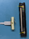
Is it one of these wires?
You need to determine if it is the terminal to carbon trace connection that is bad or if the carbon trace has a crack in it.
I don't think it is the slider, but you can check.
You should be able to test the connection by clipping your DMM lead to the connection that is bad and use the other lead probe tip to touch the carbon trace to see if it makes contact.
This slider is from my Nak tape deck but construction is probably similar.
The carbon trace has contacts on either end that go to the external solder pins. This is an example of a single channel volume slider, but construction is similar.
- If the connection is intermittent, maybe the connection between the connection (yellow arrow) and the carbon is bad or you have a hairline crack in the carbon line (green).
- You can check for a connector contact problem by connecting your DMM to the two end leads and you should measure the full resistance of the carbon.
- If you flex or move the slider and the resistance changes then you have a problem either with one of the connectors or with the carbon trace.
- If it is stable, then the problem is with the contacts on the slider itself.
- You can determine which side the problem is on by measuring the resistance from one of the ends to the slider contact and moving the slider, then try the other end to the slider. Whichever side has the intermittent Ohms reading as you slide it the end with the problem.
Last edited:
The connector on the far right with the white wire is the one in question
I removed the metal cover and with my Simpson analog meter put one probe on the connector marked in yellow, the other probe on the other side ,wiggled the stem , no change
One probe on connector marked in yellow as per your post, the other on carbon track, wiggled the connector and lost contact meter dropped and came back.
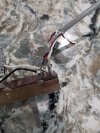
Point in question, second photo, far right top.
I removed the metal cover and with my Simpson analog meter put one probe on the connector marked in yellow, the other probe on the other side ,wiggled the stem , no change
One probe on connector marked in yellow as per your post, the other on carbon track, wiggled the connector and lost contact meter dropped and came back.
Point in question, second photo, far right top.
Attachments

Last edited:
On my photo the yellow arrows point to both sides of the CARBON track. Are you saying on yours there was no change when you connected to the metal track or the carbon?
You can find where on the carbon track the break is by checking the Ohm reading at various parts along the carbon track. It may even be where it connects to the lead out of the control.
You can find where on the carbon track the break is by checking the Ohm reading at various parts along the carbon track. It may even be where it connects to the lead out of the control.
What i mean is that testing the top and bottom of the connection it is goodOn my photo the yellow arrows point to both sides of the CARBON track. Are you saying on yours there was no change when you connected to the metal track or the carbon?
You can find where on the carbon track the break is by checking the Ohm reading at various parts along the carbon track. It may even be where it connects to the lead out of the control.
Testing the bottom of the connection to the carbon directly below it, i loose connection if i wiggle the post
I'm still confused. 
Are you saying that you have an intermittent connection between the two orange arrows, or the two green arrows?
Why don't you put some arrows on your own photos to show where the good connection is and where the intermittent one is instead of me guessing.

Are you saying that you have an intermittent connection between the two orange arrows, or the two green arrows?
Why don't you put some arrows on your own photos to show where the good connection is and where the intermittent one is instead of me guessing.