

You are using an out of date browser. It may not display this or other websites correctly.
You should upgrade or use an alternative browser.
You should upgrade or use an alternative browser.
2385 reconnect PS00 to P400 pin question
- Thread starter sendust
- Start date
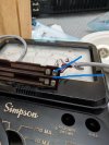

That connection from blue line to blue line is NOT on the carbon trace, it is on the wiper trace which is just a copper (brass) conductor. It may just be a feed through rivet to connect the trace to the post. You can just try to apply some flux and solder to that hole and where the hole mates with the trace and you should have a good connection. The CARBON (resistive) trace is the 1/2 black trace above it. When you move the slider the contact on the slider connects the soldid trace to the one above it. If you are on the half that has both traces as copper, then there is no attenuation (resistance). If you keep sliding it over, then you start to hit the resistive material and it effectively adds more resistance to the signal path. The other channel is just the opposite. If your slider is positioned to the right, then there is the most resistance on the other channel to attenuate the audio on that channel.
If the problem is the continuity between the two blue lines, then it should be a simple fix by adding some solder.
Apply solder here:
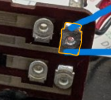
If the problem is the continuity between the two blue lines, then it should be a simple fix by adding some solder.
Apply solder here:
Last edited:

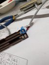
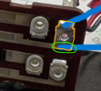
I think that you need to put some solder where the green circle is between the feed through and the copper trace. That should connect the circle feed through to the copper trace. You should be able to narrow down exactly where you lose conductivity using your meter and probes. That is where the solder is needed.
Last edited:

That is either copper or brass so it should be solderable, but you need to clean it well first.
- First, clean both the trace and the feed through with 99% Isopropyl alcohol and a Q-tip
- Next, try to clean both with a pencil eraser and see if the oxidation is removed. If not use a extra fine piece of sandpaper. (careful not to scrub too hard).
- Clean again with alcohol & Q-tip
- Apply solder flux to both areas
- Heat the joint and apply a SMALL amount of solder and let it flow between the joint
- Test again with DMM
- If good, then clean again with alcohol and Q-tip
I cleaned the area with 99% alcohol, let it dry, then used a clean eraser rubbed untill not black anymore, re cleaned with 99% alcohol ..let dry added flux, heated down on copper trace. solder runs up to connector but doesnt stick to trace. Do i need more heat on copper trace?That is either copper or brass so it should be solderable, but you need to clean it well first.
- First, clean both the trace and the feed through with 99% Isopropyl alcohol and a Q-tip
- Next, try to clean both with a pencil eraser and see if the oxidation is removed. If not use a extra fine piece of sandpaper. (careful not to scrub too hard).
- Clean again with alcohol & Q-tip
- Apply solder flux to both areas
- Heat the joint and apply a SMALL amount of solder and let it flow between the joint
- Test again with DMM
- If good, then clean again with alcohol and Q-tip
Maybe there is a coating on the copper trace. Try to sand it just enough to scuff it up a bit with very fine sandpaper, clean, then try again. Yes, you might need more heat.Do i need more heat on copper trace?
I have 2000 grit paper. I'm using 360 c for Temp. Should l go higher?Maybe there is a coating on the copper trace. Try to sand it just enough to scuff it up a bit with very fine sandpaper, clean, then try again. Yes, you might need more heat.
I tried a wider tip, scraped a bit with an exacto blade, sanded with 2000 grit, cleaned again with alcohol, dried and applied flux. heated just the copper trace, the hotter it got the more the solder runs up to the connector, nothing at all sticks to the trace.
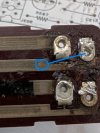
As per in the photo, can i clean and sand where the circle is and try and install a very thin jumper wire to connector?
As per in the photo, can i clean and sand where the circle is and try and install a very thin jumper wire to connector?
Attachments
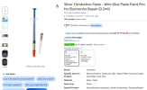
My solder is 63/37 . I will try and get the silver conductive pasteI wonder if it is aluminum? Maybe you can use some conductive epoxy?
What kind of solder are you using (60/40, 63/37 flux core...) hopefully not lead free?
View attachment 3828301
As far as I can tell, that's what it says to do. Then let it dry. Try not to get it too far down the trace so it won't interrupt the sliding piece.So I can just clean and sand a little over the solid trace and use the syringe to apply a line to the connector from trace.
Ive used the silver paste and am pretty sure this has solved my intermittent issue.
I will now put the unit back together and try to find with the scope where the left channel distortion originates.
Im not sure if there is a different way to set up the oscilloscope to see the distortion, as of now right and left look identical, is this possible it is a output transistor ?
I will now put the unit back together and try to find with the scope where the left channel distortion originates.
Im not sure if there is a different way to set up the oscilloscope to see the distortion, as of now right and left look identical, is this possible it is a output transistor ?
Ages ago, I think that you performed a test where you connected an external audio source to the Main In L/R jacks and I think you said that that was OK.
You can also connect the Preamp L/R outputs to another amplifier and listen for the distortion to see if it is coming from the Preamp.
You don't need the scope for either of these tests. Also, to make sure it is not your speakers, connect the L output to the R speaker and R output to the L speaker.
You can also connect the Preamp L/R outputs to another amplifier and listen for the distortion to see if it is coming from the Preamp.
You don't need the scope for either of these tests. Also, to make sure it is not your speakers, connect the L output to the R speaker and R output to the L speaker.
I reversed it , 2275 pre out to 2385 main in, 2275 aux for music, speakers on 2385 main. volume up on 2275 no distortion right or leftFrom that test, it sounds like the 2385 Preamp is good and both of your speakers are good. Looks like your balance control repair worked.
Now you need to try the reverse, 2275 Pre-out to 2385 Main in.