

You are using an out of date browser. It may not display this or other websites correctly.
You should upgrade or use an alternative browser.
You should upgrade or use an alternative browser.
2385 reconnect PS00 to P400 pin question
- Thread starter sendust
- Start date

It's hard for me to tell anything from your description. You need to provide a schematic reference to whatever you are describing.I replaced the resistor with a 22 ohm 10 watt
You might need to lift one side to get an accurate resistance reading.
Is this the 22 Ohm resistor that you replaced? It is in series with the transformer primary windings.
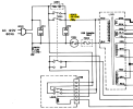
Last edited:

Yes, I removed it and it tested at 1.34 m ohms.It's hard for me to tell anything from your description. You need to provide a schematic reference to whatever you are describing.
You might need to lift one side to get an accurate resistance reading.
Is this the 22 Ohm resistor that you replaced? It is in series with the transformer primary windings.
View attachment 3839259
I replaced it and when powering up I found I have a short. As I posted I think I found it, need to find a replacement
I think it's 470k will check with schematics R702
Something else that is in parallel with it on the board is very low in resistance.

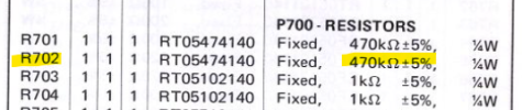
If you don't have any cable plugged into the R channel Main In RCA, then it will short the signal to ground (1 and 2).
I don't know why the other channel is different unless you installed the 470 Ohm vs 470k Ohm resistor for R702.

Did you really mean 470k Ohm, or did you install a 470 Ohm?i found a replacement 470 ohm, tested it and it read 468 ohm I installed it and it now reads 1 ohm. R701 reads 490 ohm in board.
If you don't have any cable plugged into the R channel Main In RCA, then it will short the signal to ground (1 and 2).
I don't know why the other channel is different unless you installed the 470 Ohm vs 470k Ohm resistor for R702.
Last edited:
I installed a 470k as per specs . If I unplug connector 710. The resistor is fineSomething else that is in parallel with it on the board is very low in resistance.
View attachment 3839388
Did you really mean 470k Ohm, or did you install a 470 Ohm?
View attachment 3839395
If you don't have any cable plugged into the R channel Main In RCA, then it will short the signal to ground (1 and 2).
I don't know why the other channel is different unless you installed the 470 Ohm vs 470k Ohm resistor for R702.
View attachment 3839397
If i remove power from Right board dim light dims
I see that on J709 there is continuity between left pin and center pin. if i connect J709 and J710 resistor R702 shows 1 ohm but R701 shows 490ohm, if i disconnect J710 , R701
reads 490ohm.
If i connect J709 , and remove J710 there is a dead short between J710 white wire and the yellow /black wire . I think that is my issue
Attachments

That's strange that it affects the opposite channel?if i disconnect J710, R701 reads 490ohm.
You measure a short between the two wires on the cable side of the connector?remove J710 there is a dead short between J710 white wire and the yellow /black wire .
Maybe there is something wrong with the Main in R channel RCA jack and the shorting contact is not working.
Try to insert an RCA cable into the Main In but don't connect the other end to anything and see what you read.

If I plug in an rca it gets rid of that shortThat's strange that it affects the opposite channel?
You measure a short between the two wires on the cable side of the connector?
Maybe there is something wrong with the Main in R channel RCA jack and the shorting contact is not working.
Try to insert an RCA cable into the Main In but don't connect the other end to anything and see what you read.
View attachment 3839507
I still have another short in the right amp
No short if I pull the power connector on the right side, does that confirm it has to be a component in the right side of the amp ?
You need to be a little more specific. I don't have your board in front of me to look at.I still have another short in the right amp
No short if I pull the power connector on the right side, does that confirm it has to be a component in the right side of the amp ?
- You say the R amp has a short from which connector (J710?) and pin to which other connector and pin? Are you talking about J710 Pin 1 to Pin 2 (R channel)?
- Are you talking about the board or the wire? The P700 board has pins 2 and 3 connected together on the board.
- This short goes away when you remove the power connector from which connector # (J737 on the P700 board?) or some other connector?
- No, it doesn't necessarily need to be a bad component. It could be a solder bridge, connector miss-wire.
Last edited:
When I was testing transistors the first time and as you stated my numbers were way off, I had an issue when touching the collector on the Q712, the unit clicked as soon as I touched it. I thought it was strange but I didn't notice any issues. I continued and got the readings I posted.You need to be a little more specific. I don't have your board in front of me to look at.
- You say the R amp has a short from which connector (J710?) and pin to which other connector and pin? Are you talking about J710 Pin 1 to Pin 2 (R channel)?
- Are you talking about the board or the wire? The P700 board has pins 2 and 3 connected together on the board.
- This short goes away when you remove the power connector from which connector # (J737 on the P700 board?) or some other connector?
- No, it doesn't necessarily need to be a bad component. It could be a solder bridge, connector miss-wire.
After your comments I decided to re test the next morning, l cleaned the metal that holds the 3 fuses and made sure there was good contact.
I started testing and found a lot of voltages around 80. Minus and positive. When I finally got back to Q712 and touched collector, again the unit clicked and now voltages were much lower.
After looking at the front I realized the lights were not on, my unit is turned sideways to access 700 board. I tested all fuses and found the main fuse blown or at least no continuity .it's white. I reinstalled a 10 amp fuse and restarted unit on dim watt, no issue light went dim. I noticed light was not on and no click, I tested voltage at switch and found 75. I followed wire to 22 ohm 10 watt resistor. I tested voltage at bottom and found 75. At top I found 33. I pulled resistor and it tested at 1.3 m ohms so I replaced it. Now when starting unit dim watt was bright.
I disconnected the power to left amp, still dim watt bright, I disconnected right amp and light dims like normal
I found the resistor R702 was reading 1 ohm so I replaced it and thought it may be the issue, after replacing found the new resistor read 1 ohm.
I then found on J710 the wires connecting to it ,the white and the yellow/black had continuity . After speaking to you I connected a rca to main in right and continuity now is gone and resistor R702 reads the same as R701 so it is not the short I have on the right channel.
Last edited:
I have a question for you.
Previously you posted this photo but didn't label where each connector went to on the board.
It's also hard to tell which is pin 1 (next to the groove) so I guessed.
When these are plugged into the P700 board, Pin 1 faces in opposite directions (see board layout).


Previously you posted this photo but didn't label where each connector went to on the board.
It's also hard to tell which is pin 1 (next to the groove) so I guessed.
When these are plugged into the P700 board, Pin 1 faces in opposite directions (see board layout).
- Please check my connector numbers and pin numbers. I may have them reversed. (J709 <--> J710)
- If you pull out J709, you will lose the ground reference on J710
- Were those wires in the ORIGINAL pins, several look like they have been removed and re-wrapped.
- I'm not sure the wiring is correct. Do you have a photo of them before you messed with the wiring?
- Looking at the board layout, it is like two separate amplifier circuits... there is not ground connection between the sides on the board.
I did not touch those wires, they are existing. If i read this correctly on the left J709 i should have on center solid wire and yellow/black on right pin pink wireI have a question for you.
Previously you posted this photo but didn't label where each connector went to on the board.
It's also hard to tell which is pin 1 (next to the groove) so I guessed.
When these are plugged into the P700 board, Pin 1 faces in opposite directions (see board layout).
- Please check my connector numbers and pin numbers. I may have them reversed. (J709 <--> J710)
- If you pull out J709, you will lose the ground reference on J710
- Were those wires in the ORIGINAL pins, several look like they have been removed and re-wrapped.
- I'm not sure the wiring is correct. Do you have a photo of them before you messed with the wiring?
- Looking at the board layout, it is like two separate amplifier circuits... there is not ground connection between the sides on the board.
View attachment 3839789
View attachment 3839792
On right J710 i should have on left pin white wire and on center yellow/black.
Attachments


It looks like you have the connector to J709 plugged in backwards.


- Look at the board drawing. J709 Pin 1 is towards the center of the board.
- J710 Pin 1 is towards the center of the board also.
- Signal is on Pin 1 in either case.
- Look at the notches in the plastic connector for connector orientation.
- Your signal wire on Pin 1 is tied to ground as soon as you install the wire connector because Pin 2 and Pin 3 are connected by a trace on the board.
- J710 is installed with the correct orientation.
- But, since there is no ground wire (J710 Pin 3 connects to J709 Pin 3 only) when you remove J709, there is no ground on J710 Pin 2 or 3.
- I think that the ORG/BLK wire should be wrapped to the connector J709 Pin 2 along with the shield.
- You must have messed this up when you (or someone else) remove some of the wirewrap wires (you can see it is not wrapped correctly).
- At a minimum, turn J709 so the Pin 1 lines up with the board.
- Your wirewrap connections on J709 connector Pin 2 & 3 are not good. They need to be wrapped tight with a tool because it is the wirewrap pin 4 edges biting into the wire that creates a good connection (actually smashing the wire at the edge). Your Gnd and Yellow wire will have more resistance because of this bad connection.
If i read this correctly all is good now for signalIt looks like you have the connector to J709 plugged in backwards.
View attachment 3839812
- Look at the board drawing. J709 Pin 1 is towards the center of the board.
- J710 Pin 1 is towards the center of the board also.
- Signal is on Pin 1 in either case.
- Look at the notches in the plastic connector for connector orientation.
- Your signal wire on Pin 1 is tied to ground as soon as you install the wire connector because Pin 2 and Pin 3 are connected by a trace on the board.
- J710 is installed with the correct orientation.
- But, since there is no ground wire (J710 Pin 3 connects to J709 Pin 3 only) when you remove J709, there is no ground on J710 Pin 2 or 3.
- I think that the ORG/BLK wire should be wrapped to the connector J709 Pin 2 along with the shield.
- You must have messed this up when you (or someone else) remove some of the wirewrap wires (you can see it is not wrapped correctly).
- At a minimum, turn J709 so the Pin 1 lines up with the board.
- Your wirewrap connections on J709 connector Pin 2 & 3 are not good. They need to be wrapped tight with a tool because it is the wirewrap pin 4 edges biting into the wire that creates a good connection (actually smashing the wire at the edge). Your Gnd and Yellow wire will have more resistance because of this bad connection.
View attachment 3839813
Attachments
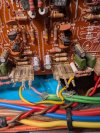
You probably should be testing from Pin 1 to Pin 2, then Pin 3 to Pin 2.I notice on J737 with wires pulled ,no continuity from pin 1 to 2 or 1 to 3
On J738 with wires pulled I read 2ohm between pin 1 and pin 3 , no continuity 2 to 1 not sure if that is normal
Both should be open since they go through the cap.
J737 looks OK.
On J737 it looks like C744 might be shorted.
Again, you should be testing J738 Pin 1 to Pin 2, then Pin 3 to Pin 2.
It should be open for both.
