

You are using an out of date browser. It may not display this or other websites correctly.
You should upgrade or use an alternative browser.
You should upgrade or use an alternative browser.
2385 reconnect PS00 to P400 pin question
- Thread starter sendust
- Start date
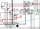

JE04 pin 3 to 2 = 75k pin 2 to 1 = 75 k
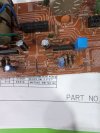
RE51 is not a resistor as per photoThanks. It looks like your board has a resistor, RE51, in the path. By your measurements, I think it is also 75k.
What is the resistor color code, and does it equal 75k (VIO-GRN-ORG)?
Attachments

STEP 5:
I want to skip looking at the two amps QE01 and QE02 for now, but I would like to follow the signal path to the connector as it leaves the board.
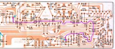
I want to skip looking at the two amps QE01 and QE02 for now, but I would like to follow the signal path to the connector as it leaves the board.
- Black lead on CE13 (-), Red lead on JE07 Pin 1.
- The PCB labels it "L" but I think it is really the R channel.
- Do you have continuity, about 0 Ohms?
That is what is called a "Zero Ohm Resistor"... a wire that jumps across the board. It just continues the trace across the board.RE51 is not a resistor as per photo
So now I am a little confused. The parts list shows that the Volume Control, RE42 is:

Without resistor RE51, I would expect that when you measured the resistance from JE04 to CE01 (+) you would only see the resistance of the Volume Control.
From the PL it looks like it is either 20k or 250k depending on whether it is "B" or "V" (whatever that means), but you measured just across the volume control from JE04 Pin 2 to Pin 3 you got 75k Ohms??? The other thing that troubles me is that as you turn the Volume control, I would have thought it would go from 0 Ohms to 250k, but you measured "black on JE04 pin 3 red on CE01 + volume off 79k full at 140k". It seem like there is a 79k resistance somewhere on that path that adds to the volume control resistance???
Is there some part number screened or stamped on the volume control. I know it might be hard to see? I can just barely see it on your last photo.
Yes 0.1 ohmsSTEP 5:
I want to skip looking at the two amps QE01 and QE02 for now, but I would like to follow the signal path to the connector as it leaves the board.
View attachment 3781129
- Black lead on CE13 (-), Red lead on JE07 Pin 1.
- The PCB labels it "L" but I think it is really the R channel.
- Do you have continuity, about 0 Ohms?
When i used pin 1 instead of 3 to test volume i got 79k at off and .09 ohm at fullThat is what is called a "Zero Ohm Resistor"... a wire that jumps across the board. It just continues the trace across the board.
So now I am a little confused. The parts list shows that the Volume Control, RE42 is:
View attachment 3781130
Without resistor RE51, I would expect that when you measured the resistance from JE04 to CE01 (+) you would only see the resistance of the Volume Control.
From the PL it looks like it is either 20k or 250k depending on whether it is "B" or "V" (whatever that means), but you measured just across the volume control from JE04 Pin 2 to Pin 3 you got 75k Ohms??? The other thing that troubles me is that as you turn the Volume control, I would have thought it would go from 0 Ohms to 250k, but you measured "black on JE04 pin 3 red on CE01 + volume off 79k full at 140k". It seem like there is a 79k resistance somewhere on that path that adds to the volume control resistance???
Is there some part number screened or stamped on the volume control. I know it might be hard to see? I can just barely see it on your last photo.
Photo of volumeThat is what is called a "Zero Ohm Resistor"... a wire that jumps across the board. It just continues the trace across the board.
So now I am a little confused. The parts list shows that the Volume Control, RE42 is:
View attachment 3781130
Without resistor RE51, I would expect that when you measured the resistance from JE04 to CE01 (+) you would only see the resistance of the Volume Control.
From the PL it looks like it is either 20k or 250k depending on whether it is "B" or "V" (whatever that means), but you measured just across the volume control from JE04 Pin 2 to Pin 3 you got 75k Ohms??? The other thing that troubles me is that as you turn the Volume control, I would have thought it would go from 0 Ohms to 250k, but you measured "black on JE04 pin 3 red on CE01 + volume off 79k full at 140k". It seem like there is a 79k resistance somewhere on that path that adds to the volume control resistance???
Is there some part number screened or stamped on the volume control. I know it might be hard to see? I can just barely see it on your last photo.
Attachments

STEP 6:
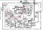
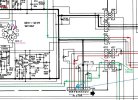
- Black lead on JE07 pin 1, Red lead on JT01 pin 1 on the PT00 Filter Amp board. Continuity?
- Black lead on JT03 pin 7, Red lead on PE00 JE05 pin 7. Continuity?
- Checking continuity on the PT00 board is a little more difficult because of all the resistors and transistors. We will leave it for later if needed.
Thanks for the photo. So it looks like there are indeed 4 controls (like it is shown in the schematic and the part no stamping). Two are 250k and two are 20k Ohms.
So why are you reading 79k Ohms instead of 0?
Does JE04 and JE05 have a wire connectors that you can remove and re-take the resistance readings? It looks like JE05 is already removed in the previous photo.
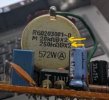
So why are you reading 79k Ohms instead of 0?
Does JE04 and JE05 have a wire connectors that you can remove and re-take the resistance readings? It looks like JE05 is already removed in the previous photo.
Wires removed pin 3 to 2 266 k 2to1 269k
JE07 pin 1 to JT01 pin 1 continuity, JE07 pin 2 to JT01 pin 2 no continuity, JE07 pin 3 to JT01 pin 3 no continuity. JT01 all 3 pins to solder joint continuity so board is fine, should i not have continuity to all 3 connections on JE07????STEP 6:
View attachment 3781151
- Black lead on JE07 pin 1, Red lead on JT01 pin 1 on the PT00 Filter Amp board. Continuity?
- Black lead on JT03 pin 7, Red lead on PE00 JE05 pin 7. Continuity?
- Checking continuity on the PT00 board is a little more difficult because of all the resistors and transistors. We will leave it for later if needed.
View attachment 3781153
Black on JT03 pin 7 red on JE05 pin 7 contiuitySTEP 6:
View attachment 3781151
- Black lead on JE07 pin 1, Red lead on JT01 pin 1 on the PT00 Filter Amp board. Continuity?
- Black lead on JT03 pin 7, Red lead on PE00 JE05 pin 7. Continuity?
- Checking continuity on the PT00 board is a little more difficult because of all the resistors and transistors. We will leave it for later if needed.
View attachment 3781153
Looking at the schematic:
Please double check continuity from pin 3 to pin 3, if still no continuity physically check the wire for breaks or bad solder.
Does that wire have a connector on each end? Remove the cable on both ends and check cable continuity for pin 3.
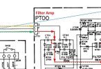
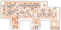
- JE07 pin 1 to JT01 pin 1 continuity - Schematic show that this is correct
- JE07 pin 2 to JT01 pin 2 no continuity - Schematic shows an open pin at JT01 pin 2 (board trace for JT01 pin 2 shows trace dead-ends.
- JE07 pin 3 to JT01 pin 3 no continuity - Schematic shows there should be connectivity, but this is for the other channel?
- Black on JT03 pin 7 red on JE05 pin 7 contiuity - That looks OK
Please double check continuity from pin 3 to pin 3, if still no continuity physically check the wire for breaks or bad solder.
Does that wire have a connector on each end? Remove the cable on both ends and check cable continuity for pin 3.
Last edited:
maybe that is the channel, there is definitely no contact at pin 3, so if that goes to a channel it is not working. How can i repair ?Looking at the schematic:
View attachment 3781308
- JE07 pin 1 to JT01 pin 1 continuity - Schematic show that this is correct
- JE07 pin 2 to JT01 pin 2 no continuity - Schematic shows an open pin at JT01 pin 2 (board trace for JT01 pin 2 shows trace dead-ends.
- JE07 pin 3 to JT01 pin 3 no continuity - Schematic shows there should be connectivity, but this is for the other channel?
View attachment 3781309