• The move to the new server is done. There are some software and database maintenance updates in process. This has us passing the hat around to help out. We appreciate any donations. Seriously, even a dollar helps. The payment page may be found here - https://www.audiokarma.org/support.html

across the bench [season-2] the electron strikes back

rogue atlas mag - 21.jpeg
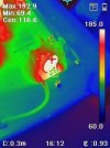
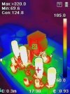
thermistor, which will be hot whenever power/system is active
rogue atlas mag - 22.jpeg
a sizeable portion of the heat will be under the minimal ventilation chassis cover

systems seems to function ok, plays music without issue and the outputs maintain their bias with no indication of aged/tired glassware drift. ready for a new home.
 
[part 2] sansui au-d55x recap

sansui aud55x - a1.jpg
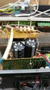
removed original power caps. also note the added heat sink for one of the extra hot locations

sansui aud55x - a2.jpg
slight physical size difference and rating
 
amp is wired for 4r load currently, looks like a headache to change over to 8r.

chances are this type of amp gets abused from an impedance point of view. wonder how that affects output tube life or circuit sanity... then again, its not like speakers have a flat impedance curve to begin with.
can you just add a switch to do it? Kind of surprised it didn't have a switch or just two output terminals from the factory.

higher than 4 ohm load on a 4 ohm tap will run higher plate to plate load on the tubes. Less current draw, but that can allow them to swing more voltage. Not a problem in triode mode, and usually not really an issue in UL mode but in pentode mode depending on the particulars, mostly how hard into clipping its pushed and how high the impedance actually is, it can let the plate voltage swing down to zero with the screens at a high voltage. Its rough on the screens, and the higher the screen voltage, the worse it is for it. If there is a screen stopper of at least a few hundred ohms it will limit the current and make it a lot less inclined to eat tubes.

also generally makes less power and may have higher distortion output with a mismatch.
 
sansui aud55x - a3.jpg
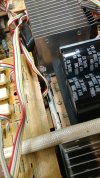
sizing up the gap over the exhaust manifold and between the 2 sets of fins

sansui aud55x - a4.jpg
obviously the new caps will not be installed into the board in a normal fashion
 
sansui aud55x - a5.jpg
side view of original cap position

sansui aud55x - a6.jpg
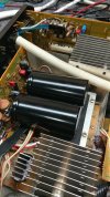
position for the new caps. lining up the pcb holes for some custom jumper wires, solid core 14ga romex scrap.
 
sansui aud55x - a7.jpg
looks like there is another 10mm of space for a taller/higher-value cap, perhaps 33000uf potential

note the thermal insulation on the heat pipe manifold, around 3mm thickness.

sansui aud55x - a8.jpg
reinstalling the initial film cap mod (8.2uf 100v each) in parallel with the larger electrolytics, much lower esr outcome
 
sansui aud55x - a9.jpg
to secure the front end of the caps, the heat pipe top plate mounting screws provide a solution

sansui aud55x - a10.jpg
scrap wide metal straps used in an avr works nicely. other options might exist but this came together without too much scrap shopping for ideas.
 
sansui aud55x - a13.jpg
the extended family group photo

sansui aud55x - a14.jpg
and behind the above camera position.

the old showroom and demo chamber were invaded by an army of vinyl. lots of sansui food in the area.
 
yam cary - a2.jpg
still adjusting the system to reduce power off noise since there is no relay circuit to short the outputs.

yam cary - a3.jpg
volume control consists of an external passive preamp so there is an extra interconnect in the overall circuit.

pair of 6.3v ct txf's, one for input bulbs and the other for output. mains txf for b+ is 120 up to 240 and then the v-doubler circuit is adjusted to desired output. medical grade iec mains filter with fuse and illuminated switch.

obviously not using the 5v mains input for the tube rectifier, so a 6550 is parked in its spot just for kicks. the large 150uf blue electrolytics in the website product photo have been replaced with smaller film, under the board. more than a few of the factory resistors have been upgraded plus a few values changed. another frankenstein project.

no new holes were drilled in the scrap donor chassis. utilized preexisting mounting locations plus one spot needed some hot melt glue which didnt stick very well. board metal standoffs also from the scrap pile, angle bracket for iec mains plug also a random piece of the convoluted puzzle.
 
asl av25dt - 1.jpg
pair of antique sound lab mono blocks with 6L6gc glassware

one amp developed an issue and after the repairs found out it also had a closer encounter with a cleaning lady service. beware the furry of a dusting wand, it looks harmless but it can be the downfall of many a bookshelf speaker.
 
asl av25dt - 5.jpg
handful of electrolytics and a consolidated board with tube sockets directly soldered. bias pots have chassis mount hardware and pcb connections.
 
asl av25dt - 6.jpg
comparing the two amps. one has a bottle or bias issue after watching the dim bulb go bright when doing the wiggle test with power active.
 
asl av25dt - 8.jpg
using a stick, bamboo in nature, probing to locate what is causing the bias instability issue

one of the pots ended up being the issue, intermittent wiper connection. adjusting the pot or any kind of physical interaction exposes the issue, dim bulb safety net makes this easy to identify.
 
Back
Top Bottom